


satanic
-
Posts
7,372 -
Joined
-
Last visited
-
Feedback
100%
Content Type
Profiles
Forums
Events
Gallery
Media Demo
Store
Everything posted by satanic
-
Does the Z145A fit on the R34 GTT?
-
Ok I'm stumped... would someone please tell me what to do then? To change or not to change?
-
I'm 19 with a R34 GT-T, insured through Just Cars for $2455.00 comprehensive (car value was $28k). That's with a zero claim history and clean driving history + 40% NCB.
-
 Timer just received... feedback left
 -
Well regardless of what's the go on the 34 (dead or un-dead), my car just clicked 40k Kms so I'm going to replace the o2 sensor just to be sure. On the other thread it was stated the following effects: 1) Increased Economy 2) No more black soot on rear bar 3) Better performance (not power, just overall engine running) disturb3d - I'm going to get a 3" front/dump pipe as well as a 3" high flow cat installed soon... I don't want to have black bumpers after each drive - will let you know if the o2 sensor changes anything!
-
So the Ford sensor will work on the R34? Ever since getting the Cat Back installed, I've begun developing quite a bit of soot on the rear bar after every drive. In the other threads, some have said that the new o2 sensor has cleared this out completely... Someone care to make a suggestion or two? I definitely know that the car is running rich now that the soot is developing. Carbon just ain't burning completely...
-
Was parked right in front of a Maroon R33 inside Chatswood Chase today... forgot to look for the plates
-
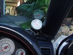
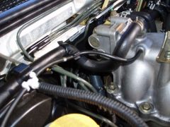
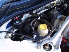
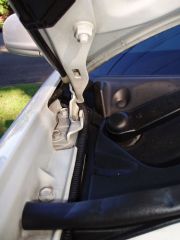
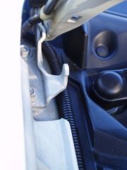
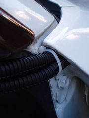
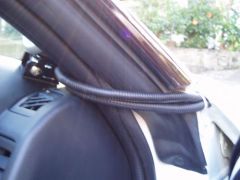
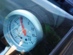
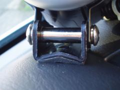
I picked up a single boost gauge and holder from another SAU member so I could regulate the boost pressure (after installing the manual boost controller for sale here as well). I couldn't find any R34 specific installation guides for this, so I decided to do all the R&D and then write this DIY up for any other R34 owners. A big thanks to Eric who supplied the gauge, and talked me through heaps of the steps. STEP 1: Positioning your gauge... * After you've assembled your gauge, position it to the exact location. * Use the base plate and the top of the bevel ring as "wedges" or stops. * "Wedge" the gauge into place and see if it stays put. * Use trial and error to get your desired positioning. STEP 2: Making sure your gauge doesn't move... * I had some sticky tape with foam backing lying around for cushioning. * Cut out enough to cover the base plate and top of the bevel ring. * These two will act as "grips" that "wedge" between your dash and A-Pillar. * The foam will also prevent slipping or movement when driving. (The ring above has also been padded with foam tape for grip purposes) NB: Using the foam not only keeps the gauge in place, but also protects your dash and A-Pillar from any damage. This will mean a 100% reversable installation. STEP 3: Running your electrical wires and tubing... * I used black plastic covers to "hide" the electrical and rubber tubing needed for this gauge to work. * Open your door and bring both the housings around as shown above. * Make sure your housings sit as high up as possible (prevents squashing). * Open/Close door a few times to test. * Blow through the rubber tubing to test air flow. STEP 4: Running housings into engine bay * Now many of you will install gauges with all the wiring going through the firewall (usually requires heaps of disassembly) - I opted for this method, it doesn't look half bad due to the black housings and more importantly it works and it saves time. * Open your door and bonnet and you shall see a few holes that are just perfect for your installation needs. Feed your housings through there and test out all your lengths (do not alter any lengths at this stage). * Again, open and close your door to test the fitting (remember to keep the housings as high up as possible). (The housings will run right into the engine bay, very neat and clean) (Black housing makes installation look almost factory, hard to notice) STEP 5: Hooking the gauge up so it works... * The above picture shows how I worked the housings so it reached the intended destination. This step can be changed to suit your likings... keep in mind the allowance for cable flex etc. * All connections to hold housing to wires etc were made using cable ties. * I completed this stage using the simplest and shortest path for the pressure hose to get to the connection. (The above shows the connection between pressure hose and main line) * Use your supplied T piece (available from Super Cheap for $2.99) and connect your pressure hose to the main line. Make sure you get the right size T piece (I actually went and bought 2 sets due to size errors). * Again, secure the fittings with cable ties to stop any leaks or chances that the hose will fly off the T piece. STEP 6: Finalizing your installation * After you have made all your connections and are 100% sure that it will all be right, you can commence final installation. * Cut any excess lengths of tubing/housing before pulling it all tight (cable ties to be pulled tight last). It is important to start this pulling tight process from the GAUGE -> DOOR/ENGINE BAY -> T-PIECE * It may be a good idea to get someone to hold the gauge in place so you can tighten everything up. Remember, the tighter everything is, the better your installation will be (less chance of movement) Since I'm not very good with electrics, the wiring up of the lights for the gauge will be done at a later stage - will write that up later. END NOTE: This is the first DIY write-up I've done... hope it all helps the R34 owners out there. If there are any suggestions for changes, all ideas will be welcomed. I'm looking forward to getting more DIY jobs done but that's later on down the track. Stan
-
From the album: satanic's Gallery
-
From the album: satanic's Gallery
-
From the album: satanic's Gallery
-
From the album: satanic's Gallery
-
From the album: satanic's Gallery
-
From the album: satanic's Gallery
-
From the album: satanic's Gallery
-
From the album: satanic's Gallery
-
From the album: satanic's Gallery
-
From the album: satanic's Gallery
-
From the album: satanic's Gallery
-
From the album: satanic's Gallery
-
From the album: satanic's Gallery
-
From the album: satanic's Gallery
-
From the album: satanic's Gallery
-
From the album: satanic's Gallery
-
From the album: satanic's Gallery


