

GTRNUR
-
Posts
1,971 -
Joined
-
Last visited
-
Days Won
1 -
Feedback
100%
Content Type
Profiles
Forums
Events
Gallery
Media Demo
Store
Everything posted by GTRNUR
-
Or you could get a stainless clamp and have some rings laser cut from titanium plate. Then weld them on one at a time using a stainless flange to keep it straight while welding, and push the pipe through a tiny bit so the holes centre and line up.
-
 An Exeedy Carbon D twin plate. I still don't see your reasoning. There is about 10mm of gasket everywhere between all coolant and oil passages. When you factor in that the gasket material is tested to 8 bar with nitrogen gas, there is no way it will ever blow a coolant leak into an oil return, or coolant to the outside world. Coolant system pressure is at most 1.4 bar, so the seal is massively over rated for the task I am asking it to perform. Gasket compression and recovery has been measured during the trial assemblies of the engine. Target gasket compression for the spacer gaskets is achieved at a little under 2/3 of head stud final torque. The remaining tension holding the head to the block focuses all compression forces on the copper gasket and O-rings. Similar O-ring/receiver copper head gaskets have been proven to hold the head on a 1500+hp RD28/RB26 hybrids. Consider the surface area look of the gasket that is actually compressed for form a seal, clamping pressure per square inch is higher than with a conventional closed deck engine. In short, the seal that the whole assembly achieves far exceeds that which standard head gasket could ever hold.
 -
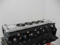
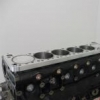
I'm not sure what you mean by blocked cooling passages on the intake side. Simply put, they aren't. Have a look at the spacer plate again. From its under side you can see the coolant galleries on the intake and exhaust side intersect with a coolant gallery that allows coolant around the whole top of the sleeve (minus about 3mm at the top).
-
The plates are machined from 6160 Alloy. I investigated using a stock gasket as from experience it did work well on the other engine. However there are a couple of issues. The first is that the stock gaskets are metal re-enforced. So to reliably cut the gasket firing rings out it would need to be put in a jig and then laser or waterjet cut. For the cost of doing that I have been able to have custom gaskets made that perfectly match the dowel positions and the spacer plate, with a far higher degree of accuracy than a stock gasket fits a block. The second issue is that the compressability and recovery data for a stock gasket is not exactly published anywhere. So to produce that data myself, I torqued 3 different gaskets up between the spacer plates to 80-ft to measure the compressability. Not only were they different in compression (by about 0.05mm), they did not compress evenly due to the seals built into it. (factor in that my spacer plate does not have a compression area around the firing rings, which would otherwise stabilise gasket compression in a closed deck stock engine). The gasket material I have used is capable of handling ludicrous pressures (80 bar+), and has published compression and recovery data. I performed compression and recovery thickness tests on the gaskets I made too, so I could predict how they will perform in an engine.
-
To deal with the thermal expansion differences between the sleeve and spacer plate I felt there had to be two highly compressible gaskets. The copper gasket does not compress at all, so it is essentially just a perfectly flat sealing surface, just like the cylinder head. So this presented no issues at all with regards to sealing, from the top of the block to the bottom of the head gasket. I am not entirely happy with having to use a silicon based sealant on top of the copper gasket to seal it to the head (threebond 1211), but this is for the most part normal practice with copper head gaskets. Alternatives being hylomar or copper spray. As I tend to do, I have since designed a better way around this issue. The V3.1 engine when it happens will have a copper inner gasket sealing the combustion chambers, and the same type of fiberous gasket sealing coolant and oil outside the combustion chambers. The challenge is making it all stay still when it is assembled. The piston design was handled by Nitto. I just told them the crown height I wanted and they took care of the rest. Running the oil ring over the gudgeon pin is a common method used for custom stroker pistons. The core piston forging they used is still an RB26 one. Yes I could have opened up the chambers a little more. But also keep in mind that this is a prototype engine, and I am reluctant to modify a Tomei head in such a manner that it might become unsuitable for use on another block.
-
It needs to be done as part of the R&D, but it won't be on this engine. Perhaps something for the v3.1 engine.
-
If I had known you were selling them I would have considered this option. I looked at what you had done here on the GTR UK forum and decided that I wanted to keep the booster (in part because I was too lazy to move the brake booster to put in a billet adapter. My solution was to use a smaller OD 5/8" clutch master cylinder, and then attack it with an 4" flapper disc to put a flat spot on it where it would have made contact with the greddy plenum. I have less of an interference issue to worry about too with my motor being 20mm taller than a rb26, not 38mm. A last option would have been to make up a smaller billet clutch master cylinder. I started on that too but the above option was the easiest.
-
Fitment is one of the main reasons I choose to develop the RB26. Retaining the AWD system with no modifications to do so is the first step in doing that. I've never heard of someone using a 2jz in a GTR and retaining the AWD setup. It would be an interesting challenge but not one I'd want to try. It poses the same challenges as an RB30 conversion, except that the exhaust would foul on the steering as well. I've done the whole engine conversion thing before, and it just gets way too messy. Another reason to use the RB26 block is that GTR's can undergo this modification without any need for a mod plate, and it fits a lot easier than an RB30. Also I believe that RB30's aren't able to be legally fitted to R34's in some states, as the RB30 stopped production in 1998, and the R34's are a 1999 manufactured car. Although I believe that many states have different rules regarding this too.
-
Yes, I have an few ideas for a dynamic cam belt tensioner system that aims to reduce ignition timing variations caused by timing belt stretch at varying high engine speeds. As a side effect of how that system works, the cam timing can be altered at various engine speeds. The challenge is fitting it in the 20m of space created in front of the engine by the spacer plate. Its on the list of things to develop, but I have too many other projects on the go at the moment. Also, I think less of "the area under the curve" than I do of moving the curve to the left. Some of the most fun I had with driving the previous engine were had while driving the engine at half its RPM range. Not to say that I don't love strong top end and no lag as well, but they are side effects of the displacement increase.
-
I kept the pipe work close to the header at first and as far away as possible from the firewall as I have a custom crankcase breather bolted to the side of the engine block. I am using the rear turbo train as a means of venting the crankcase and pulling it into a vacuum.
-
Exhaust fabrication. I used a 3.5-4" transition from the turbo, and fabricated a 4" front pipe. The system uses v-bands for all joins, which makes removing and re-fitting it a very quick and easy process. It was extremely helpful having the old RB315 there to mock up on, as there is only 1mm difference in height between the two engines. As you can see, the whole exhaust is wrapped in black lagging. I haven't gotten around to it yet, but will at some stage plumb the screamers back into the front pipe with slip fit joins to the existing screamer pipes.
-
Moving on... Time came to fit the engine to the car. Much thanks goes to Lee Holman at a local workshop called SVS, as he essentially rented the use of a hoist for 2 days. This was the first time I had done a GTR engine R&R before, I usually just pay someone else to do it. As the sump from the old engine was being used, the engine was just un-bolted and lifted off the sump. This meant no stuffing around with the front diff which was good. When I stripped back the RB315, I removed the hot side of the engine when it was in the car. This allowed me to remove the AC Compressor from the engine and rope it to the side of the engine bay, so I didn't have to re-gas the system. The reason it took two days was I found a couple of surprises when I remove the Exeedy Carbon clutch from the RB315. The locator dowel on the flywheel had a different size than the dowel in the back of the crankshaft A stepped dowel was made from a drill bit to correct this issue. The initial install was done and I discovered the clutch master cylinder/greddy plenum contact issue, so the MC was just pulled out at that point. I later had some spacers laser cut from 10mm alloy to lower the k-frame a little. This gave me the clearance I needed.
-
Yes the shuffle was a bitch to resolve, but its not the reason for the switch. The divider in the twin turbo pipe and tuning sorted that out for the most part with the RB315. The shuffle was never gone completely, but with a lot of tuning I got it to happen lower in the rev range. It would shuffle around 1900 rpm, which was below where the engine drove for the most part. It was stable above that, and would spin both turbo's up nicely to 24lb by 3700ish. It was actually very nice to drive around town in traffic, wickedly quick even below 4500 rpm. The real reason is that I have seen what these turbo's do on the 3.4lt 2JZ engines. The cam profile and displacement is extremely close to the 3.4lt testing that Sound Performance did with the 6266, 6466 and 6766 on a few other 2JZ's, the dyno results are all over the internet. Im sure you have seen them. I must admit that part way through the front pipe and wastegate pipe manufacturing I was thinking twins again. It takes so long to get it right, and making a 4" system there isn't a lot of room to move. The old twin setup would have needed to be revised as well. The dumps and front pipes were too small so I would have been after some old tomei or midori dumps and a big front pipe. Also the GTRS's would have had to be replaced with some GTX28's. If there were to be a second reason, it would be simply because it looks bad ass! The visual impact of a high mount precision combined with how this engine sounds makes all the effort of building it worthwhile it for me.
-
The valve train is good for 9k. The piston size, rod and stroke combination is the same as the SR23 stroker kits, and they rev those to 10k. Realistically it shouldn't need to go past 8k, and this cam setup should make peak torque around 6500. The rod bolts are the limitation for revs, not the rod ratio (piston acceleration etc). Dan is totally getting the idea. Its seems that many people tune RB26's to within an inch of destruction when going after big power. My thoughts are why not have a setup that can produce a good strong result a whole lot easier. Make the power goal you want and do it easily and with a soft tune. Based on calculations this setup should make over 500kw atw at about 25lb boost.
-
And the hot side. Ceramic coated Full-Race twin scroll manifold, twin Tial gates, and a Precision 6466 with a 1.00 housing. This has the engine pretty much completed and ready to swap into the car.
-
It would need at least a 10mm spacer plate, as the machining for the larger sleeves/cylinders alters the way the stresses from torqueing the head are applied to the block. If you could get it in a car, I believe you could use a 90x94mm setup. (3589.45cc), so another 240cc on this engine. Its not something I'll be trying anytime soon though. The whole point of the open deck RB26 though is to allow for easier fitment without having to use adapter plates or chisel away your bonnet framework. If I had used a stock plenum and twin turbo setup, the engine can still pass for stock.
-
Moving on again... Intake side, cam covers, gears, timing belt, and the ATI balancer all installed. I went with a Greddy intake on this engine. Not the wisest decision I ever made, as the added size of it meant there was contact with the clutch master cylinder when the engine was installed later. I resolved this issue by lowering the K-frame a little, using an alternate model GTR clutch master cylinder (that had a smaller OD around the piston), and shaving some material off the master cylinder to clearance it. The combination of all three gave me about 9-10mm clearance. I still retain the clutch booster.
-
The gasket material has been carefully chosen to be able to seal under a very wide range of operating temperatures. The compressability and recovery combined with the operating temperature capability of the of the material can easily absorb 1.2 thou of variation(the allow plate growth). According to the data sheet, pressure tests performed with nitrogen gas survived pressures of over 80 bar over 250 degrees of operating temperature. It will definitely out live the life of the engine. I didn't mention it above, but before assembly the alloy spacer plate is surface ground back to a specific thickness. Such that the total thickness of the plate and plate gaskets when installed will seal, and achieve the same height as the top of the sleeves (extended deck).
-
Finally the cylinder head is installed. The top side of the copper head gasket is installed with a smear of 3bond high viscosity sealant, to ensure the top of the gasket is chemically sealed to the head. The bottom side of the copper gasket is sealing against the top plate gasket, and the tops of the cylinder sleeves (and the o-ring area). This engine uses ARP2000 head studs, torqued to 125ft-lb. If the block were fitted with 12x1.75mm inserts, an off the shelf option exists to use ARP CA625 studs which torque to 160ft-lb. For the sake of this build that would be overkill. That's all for tonight.
-
Moving on... The cylinder head. For this engine I have used a Tomei Complete head. It is essentially a new factory head fitted with the tomei catalogue. Oversize valves with thin stems, Tomei guides, and moderate porting around the valve seats and exhaust ports. It also has Tomei's buckets, titanium retainers and springs. The cams are step 2 procams, 272 x 10.25mm. I honestly wanted more of a drag ported head for this engine with 260 x 10mm+ cams, but this was a good compromise. For the money there is a lot of good parts in the package, and to liven it up more it only needs a little more porting work. The quality of the assembly is extremely nice too, as you will agree from the photo's of the combustion chambers. The addition of the wire O-rings is the only modification I have had done. These O-rings match the receivers in the tops of the sleeves. The last picture shows the copper gasket deformation that occurs when the head is torqued. As you can see, everything is perfectly centred.
-
Now you can't see it in the picture above, but under the spacer plate there is a custom made gasket. This gasket seals the coolant and oil returns to the spacer plate. On top of the spacer plate I use a second gasket, which is designed to seal against a copper head gasket. The two fibrous gaskets function to seal the spacer plate perfectly, and also to take up the thermal expansion variations of the plate. So the plate is essentially floating between two compressible gaskets. In order to achieve the correct compression with these gaskets, the spacer plate was installed in a jig and surface ground to a specific thickness. The gasket shown on top of the plate here has been lightly sprayed with a little hylomar, my favourite gasket sealing product.
-
Before installing the plate, a Tomei pump was installed along with the cam timing gear. The mail oil gallery was also grub-screwed to seal up the oil supply lines to the main and rod bearings. Then the spacer plate fitment was re-checked with the dowels installed. (Truthfully, I trial assembled the engine 5 times... But I had to show off just how good this all looks!)
-
The two oil supply galleries that would supply oil to the head had been drilled out and threaded to receive a grub screw prior to the cleaning process. These plugs were installed now as the oil supply to the head comes from the spacer plate. Next, the spacer plate comes into play again. An oil gallery is drilled through the top of the plate, to 10mm deep, and then a 1/6th BSPT thread was tapped into the side of the plate to allow a -4AN fitting to be installed. The plate also has some custom 35mm long 15mm dowels installed here as well.
-
At the start of this V3 project, I contacted Nitto and asked them about making a custom crankshaft for me. As it turns out I was very fortunate that they had already made a custom one-of crankshaft that was going to suit my purposes perfectly. The crank is a Nitto 90mm RB26 stroke crankshaft. Rod journal sizes are Rb26/SR20, so it was exactly what I needed. I was initially going to go with Nitto I-Beam rods as well, but ran into issues with the 19mm wide bearing on the crankshaft. In short, the radius's off the journals was too large to allow the bearings to run properly. So I switched back to conventional Rb26 17mm wide bearings and H-Beams. Nitto's SR20 rods are apparently good for 700+ hp in an SR20, so they will meet my goals no problems.Rod bolts are ARP2000's. As the block had the oil squirters removed, I have had some jets milled into the rods to squirt oil from the rod journal to the bottom of the piston. This will aid oil flow to the rod journal a little, and also help with piston cooling. This is a very simple approach that was pioneered in the Porsche 917's, and proved to work well in their 1000hp engines. The pistons are a custom order from Nitto/JE. 89mm bore with a 4cc dome, and a 28mm compression height. To achieve this pin height it was necessary for JE to run the oil ring over the gudgeon pins. There is a steel support ring under the lower oil ring making the ring assembly possible. The pistons are also notched for high level valve lift.
-
Bottom end assembly. The bottom end of this engine went together virtually the same as any normal RB26 block. The only real was that the oil squirters had to be grub screwed and blocked off, as the 90mm stroke 12 counterweight crank could not be modified to clear squirters. Basically the hardness of the Nitto crank proved to be too hard to reliably machine/modify, also due to the nature of an intermittent cut while modifying a crankshaft.

