

GTRNUR
-
Posts
1,970 -
Joined
-
Last visited
-
Feedback
100%
Content Type
Profiles
Forums
Events
Gallery
Media Demo
Store
Everything posted by GTRNUR
-
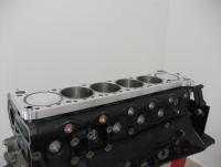
 Once the block has been sleeved, the coolant galleries are then partially filled with a composite resin. This block has been filled to 1/2 way up the welsh plugs. Final block boring and honing can then be completed. The base sleeve design has an 87.5mm raw bore inside diameter. The sleeves can be used as 87.5-88mm with a conventional stock or aftermarket gasket. Larger bore sizes require custom gaskets. The sleeves will support up to a 90mm bore. This completed block has an 89mm bore size and is setup to use a copper head gasket. A pre-assembly of the rotating assembly was performed in order to determine the correct height of the sleeves, and they were then trimmed back to suit the application and target compression ratio. Final block height was extended 20.8mm in this case, and the target compression ratio was 9:1 with a 1mm head gasket. The tops of the sleeves have a receiver slot as well, to help further improve the seal with the copper head gasket. The cylinder head has a matching o-ring configuration. When torqued to spec the copper head gasket is deformed into the receiver slot creating the ultimate cylinder seal. Last of all from the under-side, this block has also been clearance for the 90mm stroke Nitto crankshaft. Future versions of this will not require such clearancing as the cranks will be manufactured to suit the block. The clearance of the cylinders for the rods was also necessary to ensure 0.090" clearance to the rods when the crank is at 90 and 270 degrees. That's all I have time to post tonight.
 -
It will be about $13-14K for a completed block, with spacer plate, main and head studs, long dowels, and spacer plate gaskets. Its not much more expensive than an RRR block, but is obviously a lot more engine as you will soon see. I'm still a long way from that though. More testing is needed.
-
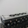
The block is then machined for the sleeves as one unit with the spacer plate and drill guide plate installed and torqued to spec. The softer alloy spacer plate is protected from swarf damage by the drill guide plate, and at this point the whole shebang is doweled together as well. The sleeves are shrunk in a freezer prior to being installed, which allows the sleeves to be worked with a little to achieve correct interference fitment. The sleeves are also chemically bonded to the engine block when they are being fitted. The new sleeve design is simular in outward appearance to an OS giken engine, but that is where the similarities end. The sleeves have multiple outside diameters, each with a different interference fit. The flanges at the top are also not only keyed together, but shimmed appropriately so as to eliminate a stress concentration that would otherwise exist due to thermal expansion and combustion pressure forces. Such forces would otherwise cause a fatigue induced failure been the cylinders. As you can see from the second picture attached, the sleeves at this point extend past the spacer plate. This plate at this stage of the machining process was 20mm thick. The sleeve are 22mm tall past the deck height.
-
Once the block is setup in the machine, the block is digitised to allow the cylinder bores to be re-positioned. The spacer plate is then bolted on, along with a drill guide plate. The drill guide plate is a 3mm thick mild steel plate which is dimensionally accurate for what will become the finished engine. The machine first machines the head alignment dowel holes.
-
So Update! I put the rest of the car back together today, bled the brakes and clutch, fitted belts, filled power steering and put on the front aero parts again. The only thing that remains is connecting a little wiring for the thermo fan controller. Fitted the TE37's again too, now wearing new Federal 595RSR's. So back to the build. I decided to build this engine into a new 24U block. There was a few reasons for this. In part I wanted to build something special for my car, and the 24U block adds to this. But I also wanted to use a 24U block so I could really see the differences between a 24U and a 05U block. During the process of converting the block to an open deck engine, a lot of material is removed from the block before the block sleeves are installed. I was going to be able to see exactly what the internal dimensions are with the 24U block. All machining of the block has been performed in a Centroid 5 axis CNC machine. The entire block has been digitalised, and a program developed to allow the design process to be repeated easily. Out of the box, the 24U block isn't really that impressive a block. The cylinder bore centres were up to 0.015" off from the correct centre of the crankshaft rod journals. To correct this the block was initially bored to 88mm so as to not have an intermittent or un-even cut happening when the sleeve boring program was run.
-
Here's a video that works: http://www.youtube.com/watch?v=lT1Hm-o5SsE&feature=related Hopefully one of the mods will be able to update the first post, and allow me to edit it so its a bit more readable. Something went wrong (like me posting the thread near midnight), and all the paragraph formatting was dropped.
-
Many of you will have read about my RB31/RB315 project. This project is the next stage of development. While this new engine's predecessor, (the version 1/2 engine) worked, it had few design shortcomings. There were some build execution issues that could have caused some potential longevity issues. There was also the machining cost issue, that would have prevented the design from ever being able to evolve into a marketable product. Too much custom componentry modifications were required to complete the engine. These things made the engine overly complicated and costly to build to completion. The new engine design resolves these issues. It uses more off the shelf components and require less modification of supporting parts (exhausts, intakes, plumbing cylinder heads etc). I also wanted to reduce the cost of machining, and massively improve the strength of the design. The version 3 design does all this and raises the bar significantly in other ways. A little over 2 years of R&D later I can now make public the completed new engine design. Broad strokes of the design are as follows: Nissan RB26 024U or 05U block can be used. New spacer plate design, 6160 billet alloy New cylinder sleeve design which supports cylinder bore sizes up to 90mm New gasket system for the spacer plate New head gasket design Off the shelf ARP2000 12mm or ARP CA625 studs The block and sleeve designs have undergone FEA to identify stresses that are caused by assembly, combustion pressures and also thermal expansion variations. Along with these changes the machining processes have been completely re-worked. This has been done to reduce the manufacturing costs, but the main reason is to achieve the necessary tolerances to take the engine design to the next level. The entire engine is now 100% CNC machined, and as a result the design can now be mass produced. In keeping with the original concept, the engine is still designed to be streetable. Although the extent of that will be greatly determined by how wild the cam and cylinder head configuration is that would be fitted to the engine. The v3 prototype engine that has been built in the first of the v3 blocks pushes a few more boundries. The engine is quite possibly the first 3.4lt RB26 based engine ever made. Full specs are as follows: RB34/24U - 3.4lt (3360cc) Open Deck Engines V3, 20mm Open Deck spacer plate block Custom Nitto 90mm crankshaft, with SR20 rod journals Nitto SR20 h-Beam rods, with custom oil jets Nitto/JE Pistons, 89mm bore size, 8.9:1 compression Tomei Oil Pump Tomei Complete Step 2 head (Tomei manufactured head will all their top shelf parts) High Octane sump Greddy Intake plenum Full-Race twin scroll / twin gate manifold Two Tial v-band gates Precision 6466 CEA twin scroll turbo, 1.00 housing Custom 4" turbo back exhaust, to 90mm trust titanium exhaust. The fuel system, ECU and electronics are currently the same setup as per the V2 engine so as to allow the engine to be started and run in quickly. They will be upgraded in time once the run-in is completed. The engine was started for the first time today. It is running a little rough when the throttle is cracked open as it wants a lot more fuel. I've since fattened up the map a little and it now seems ready to put on a dyno for run-in and testing. Here are a few pictures and video of the engine running. http://www.youtube.com/watch?v=lT1Hm-o5SsE&feature=related The complete build will be posted over the next few days. I have a huge library of photos to review. I still need to bleed the brakes and clutch, put on the ac and power steering belts, change the tyres, and put the inner guards and front diffuser back on the car, so there is a fair bit to do before it's driven. Cheers, Ian Swinkels
-
Final post for the open deck V2 engine. The engine is now out of the car and has been disassembled. The last attempts to get more power out of the engine started producing some worrying results. Specifically the EGTs were climbing through the roof. This had me thinking that I had burnt a valve or something. The motor also suffered from valve float above 6500 RPM, which is the main reason I couldn't break the 400kw goal. 385 was the best I could do. Initially I had put this down to issues with back pressure as the Greddy extension dumps are only 70mm at the flange to the y pipe, but this combined with valve float meant that revving it was just not making power. Cranking more boost into it made the issue exponentially worse as well. Higher boost caused the power to drop off sooner. I tried compensating with valve timing and while spool became better, power did not improve. Finally when EGT's began climbing I realised where the issue was. The final results of the tear down turned out to not be as bad as I expected. Burnt valves on cylinders 1 and 3, no collateral damage at all. In hindsight I should have used a properly developed head, instead of a reco-second hand head. The head had failed its vacuum test initially too, so the valves were probably a little bent before it was stripped and re-assembled. I suspect due to the head having been put on the bench with the cams still in it. I am especially happy with how the modified crankshaft has held up, as due to the offset grinding of the journals (to increase the stroke to 87mm and reduce the journal size to 48mm) the nitride surface is no more. All up the engine has about 26,000km on it. About 10 of those aren't terribly savage, but the rest of the time I gave the engine a hard time daily with up to 30lb boost. The rod journals still look like they did straight from the machine shop. So that's all for this engine. I have learnt a lot from the process, and 2 years down the track I have now developed a V3 engine. I'll be posting up the build thread a little later tonight. Cheers, Ian Swinkels
-
Piglet's Rebuild Of His Busted Tomei 2.8
GTRNUR replied to Piggaz's topic in Members Cars, Project Overhauls & Restorations
Hard to say how strong the getrags are exactly, there is too much talk and not enough actual information. The way you drive you probably wouldn't have any problems. I've only heard of two that failed. One was in a RIPS drag car that broke the gearbox housing with slicks during a launch. The other was a lubrication failure of 6th gear during a top speed run, most likely due to centrifugal forces throwing oil away. -
Piglet's Rebuild Of His Busted Tomei 2.8
GTRNUR replied to Piggaz's topic in Members Cars, Project Overhauls & Restorations
Hang in there Paul, sure it can be heart breaking with things break but its part of playing with performance cars too.... I'd like to know how noisy a holinger is compared to a normal box too for streetability. If your not driving the car every day, who cares if its not a lot of fun in 3 point turns. Have you thought of using an R34 getrag? With the R33 diff ratios it would handle more power, plus they are nicer to drive than an R33 box and cheaper than a holinger or built box. -
Can you tell me what needed to be done to the -5 housings to get the GTX cartridge to fit? I have a pair of GTRS's that would benefit from this change.
-
I made the same mistake and used a greddy plenum on my new setup. Its a headache that could have been avoided by using a stock or maybe a nismo plenum in my case. I suspect this is one of the reasons RIPS always use a custom plenum on their RB30DET gtr engine setups. They can make the plenum sit a little lower so they don't have any issues with fitment. The same probably applies to their sump setups, so as to clear the cross member/swaybar and power steering return lines. Along the way I did discover 2 versions of GTR clutch master cylinder. One with a smaller OD for the cylinder but with a 5/8th piston still. This gave me about 3 more mm room between the plenum and the master cylinder. Every bit does count when your trying to make something big fit where only a 2.6 was supposed to fit.
-
And unattended children running amok at car shows. I saw a kid dent a show car by heavily leaning on a car one time. Parents....? Nowhere to be found!
-
People that have to touch the paint on a car when they are having a look.
-
I'm with superben. Displacement adds drivability. Having said that I have sacrificed some low end torque with my new setup for the sake of having a nice sound to listen to, and gone for some big cams and a massively high flowing exhaust. I think many of you focus too much on which rod ratio is better and are afraid to go much shorter than stock. In small piston engines like the RB's it doesn't really make a lot of difference with reliability/longevity of the motor. Its not as though the engine is throwing around 4" bore pistons. The SR23 engines with 137/91 = 1.5, with a 89mm more is a good example. There are advantages for the short rod ratio engine in a street car too. The main one that comes to mind is that a radically ported head will work well at lower engine speeds, due to increased piston speeds and higher vacuum pull. This is part of the reason Piggaz's combination works so well.
-
I looked around for this information for a while too, and finally when throwing out the shipping box for the turbo found that the information was actually in the box. Here I was thinking Precision shipped turbos with no information like Garrett do. There is an inner and outer box, and al the necessary information I needed was between the two. Tear you box apart and you'll probably find it too, along with stickers etc. If there is one thing the Precision vbands could do to improve their setup, it would be to make the vband positively centre on the housing by machining a matching edge on the housing and flange. Such a simple thing to do, and it greatly improves the seal, load carrying capability and guarantees pipework is centre off the back of the housing.
-
Remove the flywheel seal retainer, main stud cradle, and all the bolts on the pump. Then lift the crank and pump out together. Once the crank is out of the block, you can get a claw puller behind the gear and take it off the crank without destroying it. Take it to an engine workshop and have them do it if you don't have a claw puller. The other option is drill through the gear in multiple places down to the woodruff key, and then break the gear with a cole chisel. I prefer the non-destructive method, saves you buying a new gear that way too.
-
Egt Sensor Location On Twin Turbo Rb26?
GTRNUR replied to Behind Horizon's topic in Engines & Forced Induction
Yes correct. Although its a 18x1.5 down to 12x1.5 adapter. Not 16x1.5 like I said before. http://www.ebay.com.au/itm/BASSANI-ADAPTERS-REDUCE-02-O2-SENSOR-PORTS-BUNGS-18MM-TO-12MM-HARLEY-MODLES-/141083999349?pt=Motorcycles_Parts_Accessories&hash=item20d942fc75 Many narrow band are also 12x1.5. Some are 18x1.5 but all widebands are defiantly 18x1.5. -
Egt Sensor Location On Twin Turbo Rb26?
GTRNUR replied to Behind Horizon's topic in Engines & Forced Induction
Im not on the UK forum much lately... too busy with work generally. I believe it is the rear dump that has the EGT sensor in the BNR34's, its there for ease of placement and access. Not for any other reason. Its quite cramped in that area of the car as you know. Yes you could buy some standard dumps from a vspec, The R32's are a cast dump so you can't easily weld a bung for the 16x1.5mm sensor probe to it. Best to switch to an after market dump and if necessary tig weld on the sensor bung in the appropriate position. Yes both dumps have a narrow band EGT port. I used an adaptor from the 18x1.5mm to the 16x1.5mm that is the standard GTR EGT probe thread. I just welded a few tangs on around the inside of the adapter so that the sensor probe wouldn't fall inside the exhaust, and bolted it in with a copper washer seal. -
Egt Sensor Location On Twin Turbo Rb26?
GTRNUR replied to Behind Horizon's topic in Engines & Forced Induction
A standard R34 Gtr run the EGT sensor in the dump pipe before the front pipe flange. They will read around 800 degrees most of the time under full load and idle down to 400 and the go off scale below 400 when you can shutdown. Its not a tuning aid, its a run down aid after giving the car a flogging. I ran an EGT in the narrow band position and saw 850 -900 degrees under full load, but really the maximum temp is determined by how long you hold full load. I advise against running them in the manifold or the turbine. Thermal expansion differences between the iron of the turbine and the Inconel of the sensor mean you always end up with an exhaust leak. That is unless you run no heat shields on twin manifolds, run a single manifold, or you really enjoy pulling your car apart to fix exhaust leaks. Sensors in all the runners 1" from the port is the only way to get effective data to use as a tuning aid, but the same issue with leaks caused by thermal expansion still applies. -
I noticed that you ran a pod filter in the engine bay in the early days with the car, and have since revised it so the filter is in front of the left front wheel. Do you have any pictures that more closely show you relocated turbo air intake? Did you have any concerns with water on the filter in the low location from wet weather driving, or do you have a rain shield around it?
-
No they aren't an off the shelf item. I drew up some spacers in CAD and had then laser cut from 10m alloy plate. I can email you the CAD file if you like and you can get some cut out at any workshop that laser cuts sheet metals. Spacers will upset the roll centre of the front suspension, but this is easily corrected with after market ball joints or roll centre correction spacers. Another side effect of spacers is that it limits where you can route your 4" exhaust, as the rear gearbox get in the way a little (discovered this today). Its going to require some heat shielding modification, and a mile of header wrap as the pipe has to be run closer to the chassis rail than I'd like. With 3.15lt of displacement the best I achieved with GTRS's was 24psi at 3700 rpm and around 200kw atw at this engine speed. The GTRS's spool basically about the same as a single TO4z (800hp rated setups). Most people that drive these turbo setups on 2.8lt hate them. On 3lt+ the GTRS's suffer from shuffle issues. Only the old school T04z is moderately immune to being problematic. Frankly these are old school setups and you can do much better with a single precision or borg warner turbo. I think you have the wrong turbo setup for a street car. Like everyone is saying, you won't see full boost till very late so it will be a pig to drive. Decide on a power goal and build the engine to meet that goal. Seems you have put the cart before the horse by purchasing those turbo's...
-
Except that with a GTR and especially with a welded on sump extension, the sump would be just about making contact with the k-frame when you use lower mounts. (not good considering how a motor moves around when its running). Also the sump section would protrude past the k-frame so it would be exposed to being damaged by speed bumps.
-
An OS giken RB26 based motor will fit under the bonnet with very little work, and can retain the timing covers. Just some lengthening of induction and exhaust pipes. I believe they are 25mm taller than stock. That will fit a R34 GTR with no modifications to the bonnet or engine mounts. In an R32 you can lower the k-frame 5-10mm with some spacers and it will fit fine. Keeping with the stock intake plenum is a good move if going 3lt+, as its just a lot less assing around to get things to fit. I'm currently fighting with my new setup trying to retain my clutch booster because I put a Greddy plenum on the new spacer plate engine. The less custom you go, the easier it is to get the car running. More reliable and easier to work on that way too. Consider using 260x10.2 cams or even with more lift. Your stroker motor will love to breath deeply at lower revs and it will make it better to drive off boost, as well as it will be less laggy. The porting work should be as far as you can take it. The largest possible ports you can go. Basically a drag porting setup. It will still drive well at low speeds despite the slower low RPM air velocity as the stroker motor pulls a much stronger vacuum than a 2.6lt would. 280's are way too big, and are best suited to motors that rev past 9000 to make power.
-
N1 24U Block Oil Galleries Size?
GTRNUR replied to ToF's topic in R Series (R30, R31, R32, R33, R34)
Only the builder can answer that question, unless its a crate N1 motor.

