

GTRNUR
-
Posts
1,971 -
Joined
-
Last visited
-
Days Won
1 -
Feedback
100%
Content Type
Profiles
Forums
Events
Gallery
Media Demo
Store
Everything posted by GTRNUR
-
I know a way it can be done! But, expensive beyond your worst nightmare would be the first reason you wouldnt do it. The second is what zebra said. Very smart move! Third... save your money and survive your P's with the small amount of points they give you. The if you want something faster, just go and buy it once your off your P's.
-
 I've heard mixed reports about the hollinger. The good is they are bullet proof, ultra fast to shift etc. The bad was (as I was told from someone else with a hollinger and 800+hp), the car lost what street manners it had left. Thats fine if you use the car as a toy that you occasionally go for a blast on the street or race track. But you cant drive your mum to the shops in it anymore. Based on what you said the cars fuel consumption is though, Im guessing its a toy so you will probably love it.
 -
Great stuff! It reminds me of the old school drag racing headers they use on some of the radically modified VW naturally aspirated engines. They would have a long merged collector and just a bit after the collector they would put in a venturi pipe, followed by a stinger exhaust tip (that looked like a big trumpet). The venturi would be connected up to the engines crankcase breather, and at high RPM the exhaust gas velocity across the venturi would actually pull the crankcase into a vacuum.
-
I have the same exhaust on my car. They are a 90mm pipe diameter but use an 80mm flange at the cat. For max flow I cut off the 90mm cat flange and made a slip fit so the 3.5" cat slips over the 90mm pipe. Works a treat. Sounds wild too. Put this system on your car and you go looking for underground carparks and tunnels to drive through!
-
Thats the opposite of what I see. My cold start AFR is 13.4:1 as that is where most heat is generated and also where peak torque is. This richens out to around 12.8 once its warm. The injector pulse value stays more or less the same, but the air temp change directly affects air density, so it goes rich. I could lean it out but the side effect is the injector pulse width gets too small and then the bad spray patern of the injector causes a random lean miss (at idle). I prefer the smoother running as opposed to being enviromentally friendly. Given the opportunity I would switch to a set of ID1000's so the pulse width's can be pulled back a lot further.
-
Nitto Headgasket Failed What Should I Use
GTRNUR replied to grygtr's topic in Engines & Forced Induction
1. Surface prep of the two mated surfaces can not exceed 3 thou, or crush will not seal the layers of the multi-shim gasket. 2. Hylomar is your friend. My feeling is that virtually every brand out there is probably pretty good, and that the majority of failures that occur with builds (that are not factory) are all either caused by bad machining or bad assembly technique. The best product in existance is doomed to fail if these two arent correct. -
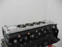
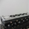
What exactly is that piece of debris in front of the valve stem. It looks like a piece of the port, as in aluminium that has been cracked away from the head casting when the stem was pressed in. If it is aluminium, it is likely that this port isnt where your trouble started. I'd wager that some or most of the other ports would have similar damage, and possibly a few bits missing from around the ends of the valve stems. Im thinking the machinist used the wrong interference fit for the valve stems or incorrect assembly method to press the guides back into the head. A tight cylinder? Unless the machinist forgot to check the piston/bore clearances I doubt its the cylinders that were at fault. Im guessing colateral damage as a result of debris from the ports ended up causing the damage. I'd be pulling the valves from the head that marry up to the damaged cylinders and inspecting the ports and combustion chambers. Debris from the ports have probably hammered into the head and piston crowns in the quench pad area too. Pictures of the combustion chambers for the damaged cylinders with the valves removed, and the damaged cylinders and pistons in the block will reveal more.
-
Most lag issues ive seen are because of air leaking from the induction side of the engine somewhere between the turbo's and the throttle bodies. I recommend blocking the hose from the twin turbo pipe to the intercooler with a plug and then pumping up the intake manifold with an air compressor and checking for leaks. You will spot most leaks with just a few PSI of pressure but you should pressure test to about 10psi above your target boost pressure. If you find any leaks you should re-set your actuators to stock positioning, or you will end up overboosting on your first test drive and break off turbine wheels.
-
Idle Hunting After Hks Twin Power Installed
GTRNUR replied to zoom's topic in Engines & Forced Induction
I have a slightly different theory. While I havent seen the twin power CDI before, I have seen this sort of behavior with other CDI's when the ignition triggering is set incorrectly. The AEM CDI's and MSD CDI's have configurable rising or falling edge triggering. If it is set incorrectly, you idle advance will drift by the effect of the dwell angle the ecu is sending to the coils. This is most noticable at idle, and not noticable at all at higher rpms. Im pretty sure the R34 coil packs contain a dumb ignitor module and are falling edge triggered. If you are triggering the twin power CDI from the output of the R32/R33 ignitor, then that could explain it. Re-wiring to have it trigger from the ecu directly could resolve the issue. You wont be able to spot this ignition drift with a timing light aimed at the balancer timing marks as the flurry of sparks the CDI delivers at low RPM makes exact timing impossible to read. The AEM CDI's allow you to disable multispark to set the base timing. I have no idea if the twin power allows you to do the same. I'd figure you would just bypass the twinpower to set the base timing and then re-connect it afterwards. -
Summer has nearly come to an end where I live so tuning for me has gotten a whole lot easier. The ambient air temp outside today is 27 degrees, which is a lot better than the 38 I was seeing a month ago. I still see high air temps after only short running time. Typically above 50 degrees the moment the engine is up to temperature. Sometimes over 60 when stuck in traffic, and never less than about 52 (on hot days) when cruising on the open road. But what is being read here is the plenum temp, not the air temp. As the climate has cooled down a little im not as concerned with air temp corrections as I was, and am more so focusing on getting better transitions into different load bands by moving my load and rpm scales around. I will definatly be relocating the air temps sensor to 1/2 way up the return pipe from the intercooler next time I pull the hoses off the car. I might try sourcing the Mazda air temp sensor as well, and give that a try too. As for the 3rd row with air temp vs setting vs boost, thats something ive yet to play with as well. If I had to guess I'd think it was boost control related, and not many of us are using the FC's boost control feature so it will probably do nothing at all. That it mentions boost for an L-jetro map does back up that guess. Maybe Trent could confirm?
-
Its a good idea to check the earth quality between the engine and the chassis, and also make sure you earth the tag that is part of the coil loom to the engine. A lot of people leave the ignitor flapping around 1/2 bolted onto the coil cover in an effort to keep it cooler, however the bad earthing is more likely to cause the thing to fail than actual heat. Technically, differences in earth potential and back emf from the coils blows up the drivers inside the ignitor.
-
Im pretty sure they are, or are at least compatible. Ive used a 33 gtr ignitor on a R32 RB20 before and it worked.
-
Yeah sorry I was 1/2 asleep when I posted that question and didnt notice you mentioned GTR. Being an R32/33 I'd be looking at getting hold of a loan coil pack ignitor for testing as well.
-
More information needed. What kind of RB is it? RB20/25/26? If its an R33 is it a series 1 or 2? If it is an RB26 is it a R34 engine? So you moved the coil packs, and the dead cylinders didnt move. Did you try doing the same with an injector? Trying the stock ecu is definatly worth doing. At the very least you may eliminate your wiring if it does run on all 6 with the stock ecu.
-
34Gtr Diffs In A 33Gtr?.
GTRNUR replied to rockabilly's topic in Suspension, braking, tyres and drivetrain
I agree. I've been messing around with my economy tuning a lot lately, and basically fuel consumption increases exponentially with speed. My light load cruse injector pulse with is about 2.2ms at 60km/h, 2.6-2.7 @ 80-90km/h and around 3ms at 100km/h. I managed about 8.3lt/100km on the last long drive including some exuberant driving. I have tried setting up the ecu map for a higher speed cruse at 120ish but fuel economy goes down hill quickly. From memory 120km/h was about 3.4ms. Also, engine response under track driving conditions suffers because you end up with a lean spot in the middle of your map at the new higher cruise RPM. I think that to get away with your idea of taller diff gears, you will need to lower or widen your engines torque range. So more mild cams or vcam, and possibly higher compression (not what you want to hear after a rebuild). If your cam timing could be optimised to make peak torque much lower in the rev range, the engine will also be able to be tuned leaner for the lower RPM. Just another thought too keeping in mind one of your previous posts, but R34 diff gears would take you in the wrong direction with regard to keeping up with the evo's while accelerating out of the corners. -
Awesome stuff!
-
Granted that HKS and Trust make some very good manifolds, they and virtually every manifold I've ever seen follows the same approach regarding boost control. That being they all vent exhaust gas pressure from the collector. The angle that the gasses vent from the collector varies from manifold to manifold. Books ive read on the subject will tell you that gas flow at the collector should ideally split down the middle to flow gas while maintaining maximum velocity at the collector to either the turbine or to the wastegate port. And while this works it still isn't optimal as when the wastegate is closed there is turbulance generated around where flow splits off to the wastegate port. So they work well once the gate is open, but not ideally until then. Ive also seen a system that used a gate attached to only one of the primary header pipes. This works well in not causing gas flow turbulance at the collector, but can have boost control issues at the top end of the RPM range. Ideally you would have a gate on each primary header pipe. The approach I see being done here is very different to all conventional thinking. The collector is designed as a typical precision merged collector. Each wastegate port in the collector then extracts gas flow at the collector from the flow stream for each primary pipe. At this point in the collector is also where gas pressure and flow are at their peak. These two things are important for 2 reasons. Peak flow means the least chance of gas turbulance before the turbine, and peak pressure meaning highest flow to the gate ports when needed. While the gate ports in the collector are at 90 degrees to the gas flow, they scavenge equally from each gas stream from each primary. Next a venturi effect is used to create a low pressure from the dump pipe, through the open gate to the gate ports in the collector. This venturi effect will increase with engine speed and gas flow. So the more power the engine makes the more effective the boost control will be. So at least thats how I think it works! Now I know there isn't an off the shelf manifold anywhere in the world that will do that. As for the results, we will see soon enough.
-
My final analysis. As has been covered, here-say says that the stock 8 blade pumps flow the highest, followed by the RB30 pumps, and then the N1 pump. As for actual flow data, none seems to exist. However, it is known that the standard pumps works as designed on the standard motors and the N1 pump work well on modified motors that rev. It is fairly safe to say that being an N1 part it will have been designed to be effective on an RB26 at 9000 RPM. Though we can all be sure it is the pump of choice for engines that rev to and past 10,000 RPM. It has been my experience that even stock GTR's struggle to keep cool in traffic driving conditions on a hot day (36+ in the sun), when the aircon is running. Unless sustained speeds above 80km/h can be maintained, temps tend to run away up to 85-90 degrees, which is well above that which the thermostat is trying to regulate too. This is because ambient air temps are too high to sufficently pull enough heat from the coolant. The goal of what I have been trying to achieve here is to get a cooling system optimised to the point that it actually can maintain engine temps at a thermostat regulated temp, even on hot days and also with a modified engine. And according to my latest test data I have come very close. The other factor I am trying to achieve is that my stroker engine produces usable power much lower in the RPM range. Cruising in 5th or 6th at 1800-2000 rpm at light throttle at 80-100k's is where I am picking up great fuel economy, so I am trying to balance the cooling system to be effective at this speed. On long drives (in the heat) it is effective, but add some stop-go traffic and it takes some driving to pull that heat back out of the coolant again. I believe it is also safe to say that the pump flow rate vs RPM are not linear. Though going on what we know with the N1 pump, it is likely to sustain flow at a higher RPM without (or with less) cavitation, while still flowing less than a stock pump at a lower RPM. This table show the crankshaft RPM and the associated RPM of the pump for each type of pulley. Crank Size Belt Speed/Ratio 2000 3000 4000 6000 7000 8000 10000 RB26 140mm 4PK875 1:1.07 2140 3210 4280 6420 7490 8560 10700 RB30 114mm 4PK850 1:1.315 2630 3945 5260 7890 9205 10520 13150 VG30OD 100mm 4PK835 1:1.5 3000 4500 6000 9000 10500 12000 15000 I have tried these combinations on my RB315. At present I have a billet VG30 overdrive pulley on the pump and it seems to be producing the best result (for my application). Crusing around yesterday in 35 degree heat with the air con blazing a nice 20 degrees, engine temps only crept up to 74 degrees when stuck in traffic. Cruise below 70km/h was 72 degrees and at 80 degrees temps dropped to the 68 degrees of the Nismo thermostat. I am still using a clutch fan with the standard R34 fan which also is obviously picking up speed as a result of the pulley size change, though there is no noticable loss in response. I put that down to the engine having torque to spare, or also the fact that once rolling and incoming air is essentially flowing into the front of the engine bay naturally, the fan is pretty much free spinning anyway. The engine still retains the water to oil heat exchange, so I am also seeing lower oil temps which is nice. Generally they max out at 80 degrees after sustained driving, which is ideal as above that viscosity does tend to drop off rapidly. (still using mineral oils for the moment). I'll add that back when I had the RB26 in the car, crusing at 100k's in 5th would produce much higher oil temps than cruising at the same speed in 6th. I'd put this down to the oil that was squirted to the bottom of the piston crowns pulling more heat from the engine at higher rpm. Or more accurately at higher RPM more heat was generated. So while my stroker engine revs much less than a stock engine does at cruise speeds, the seems to be being transferred to the coolant via the block more. Then there is also the grey area ive introduced with a tomei oil pump too... As it is very likely that the oil squirters in my engine operate virtually all the time, as even at 1800 rpm the oil pressure is 4kg/cm so the squirters will be operating. So for the moment my current setup will remain with the VG pulley for the remainder of summer. Considering I tend to shift gears at no higher than 7000 RPM generally, pump speed shouldnt be an issue. But in winter I believe I will swap to the RB30 pulley, and still maintaining propper engine temps. My opinion would be that for any stroker engine that is intended to stay below 8000 rpm, keep a stock pump. And for 3lt engines switch to an RB30 pulley. And only run the VG30 underdrive pulley if you live in an hot climate, and when you do, limit the use of your maximim RPM or risk throwing belts or breaking the pump. There are those out there that claim they want to maximise response and minimise the power and response losses from driving the standard cooling system. Really though, all the power and response in the world is pointless if you can not used it for more than 5 minutes without it overheating. So a cooling system should always have capacity too spare to properly cool your engine for its given performance.
-
Will My Sard 700Cc Injectors Support 400Awkw?
GTRNUR replied to Marko R1's topic in Engines & Forced Induction
Im using 700's. Based on the scaling of my MAP sensor and running 1.6 bar with a rich 11.5:1 afr I think there is room for well over 400kw from the 700's, provided you can make that power below 8500 rpm. My calculations show that at 1.7 bar boost and at around 8000 RPM i'll be brushing up against the 100% duty limit. My hope is that i'll achieve 450kw at the tyres with this setup, and at the most with the addition of water/methanol injection. Im using a nismo in tank pump too. -
Now thats a hard to come by item. I wouldnt mind one of those myself! Do you have the extra fin assembly that goes over the sheet?
-
I see he has replaced all the bolts on the engine with grade 12 allen head bolts. Its a nice touch.
-
I'd like to have a chat to your builder John about what he is doing with this setup. Ive read a lot about optimising the squish area of the combstion chambers, and specially designed "squishy" pistons that aim to compress the air fuel charge into the perfectly shaped combustion chamber and maintaining a high compression ratio at the same time. Like all hot-rodding idea's concepts arent new, but at the same time they arent common either as it takes time and skill to setup the engine properly. The information I read about it was relating to SB Chev's and nascar in the 80's. To a degree the RB26 in stock form does apply some of the concepts, but in reality as a mass production engine they arent all perfect or 100% identical by any means. Most blocks have un-even deck heights from factory. Im guessing that is a 7 thou positive deck, which will mean that with an un-compressible 1mm metal head gasket he is aiming for around 33 thou head to piston clearance which is about as close as anyone would dare. Especially when you factor in the big HP nature of the engine and that to do so you will be running much larger than stock clearences on the crank and rods. It will be interesting to see what kind of rods you use as well, because when things are setup with working clearances being this close, even thermal material expansion can ruin your day. Im thinking they will be titanium.
-
Getting a little off topic here, but anyway... Assuming you are walking in a slow circle past a fan first, and then past a furnace. What you will experience is a nice cool down, followed by a heat up cycle again. Going slowly means more cooling time when in front of the fan, and also more heating time when in front of the furnace. The result will be that for a given time your body temperature would have the largest temperature variation from its hot to its cold state. Now if you were to run the same circle (and assume you dont generate any of your own body heat). Hot, Cold, Hot, Cold, etc very fast! You will have less time to cool down per fan pass, and less time to heat up per furnace pass. This means your temperature over time will vary less from its hottest to its coldest temp. As for which wins the thermal battle, that is determined by how efficent the fan is and how much heat the furnace generates. We have left out the thermostat here as well, which is designed to maintain a maximum level of cooling. So by varying the fan speed (in our little story), we could limit the cooling rate and vary the average body temperature. The limited information that I have come across so far is that the 8 blade pumps flow the most, then its RB30, and then N1. Still this was just a comment that someone made on a forum thread somewhere, no data was provided again. And it wasnt from someone with a knowledgable reputation like Trent of Status either. I dont think the differences between the RB30 and N1 can be identified in just a picture. Blade angle and exact size are instrumental to how it works, what and pressure it will achieve at the pump.
-
I agree with you there Tony, except for the boiling water test... Most people with something serious under the bonnet are also already running a tripple core radiator as well and typically have twice the coolant capacity and much more cooling surface area. If you factor in this with the fact you are generally going faster at a higher RPM and your cooling systems efficency goes up exponentially with speed.
-
Great looking impeller you have there. I guess you had to slot the disc and tig weld the blades both sides of the disc. And then probably machine it round and flat again. Very fiddly work.
