

GTRNUR
-
Posts
1,971 -
Joined
-
Last visited
-
Days Won
1 -
Feedback
100%
Content Type
Profiles
Forums
Events
Gallery
Media Demo
Store
Everything posted by GTRNUR
-
Ive heard of those also being used to balance individual injector trims based on EGT. The exhaust temp is measured by taking a reading off the manifold next to the head end flange. Individual injector trims can then be adjusted to balance out any differences in injector flow.
-
Flywheel lock, to allow the flywheel bolts and harmonic balancer bolts to be torqued properly when the engine is out of the car. This is actualy a lock for a vw engine but fits perfectly on RB's as well, and costs about $5-10 from most old vw parts places.
-
This might be useful. http://www.pape.ws/allan_and_rosanne/Z-Car...%20Stroker1.htm
-
 I hadn't come across that information but it confirms im on track with a 0.060" head gasket and around 14-18 thou protrusion. The data I came accorss for plain copper head gaskets is different again. They recommend 10% of the gasket thickness as the protusion clearance, as the copper doesnt compress like a conventional gasket does. The head stud re-torque has now been done, and I have hot run the engine a few more times. After re-setting the ignition timing (which was out 10 degrees) and adding a little extra fuel in the idle cells on the fuel map the engine is now purring sweetly at 875-900 rpm. I really like the tomei oil pump too and how it delivers good flow at low rpm. Idling at 875 rpm it sits on about 40psi and at 2000 rpm which will be the (optimal cruise rpm) it jumps to 75psi. I wanted more oil pressure lower in the rev range, to help the engine tolerate two negative aspects of the shorter rod ratio. That being rod bearing side loads and pistons rocking in the bores. So I've run the rod bearing clearences towards the loose end of the recommended scale, so that combined with the extra pressure at low speeds should deliver good oil flow at the bearings keeping them nicely cool and safe. The higher oil pressure will also have the oil squirters working earlier in the rev range, helping lubricating the cylinder bores well as well as cooling the pistons better. Thats all for now. Ian
 -
I used 0.8mm stainless wire. The ring slot in the head is 18thou deep leaving around 14 thou of the ring exposed. The sleeves in the engine are a little taller than the spacer plate too which has the same effect o-ringing. Time will tell if this is the correct sort of setup. There isnt a lot of information around on how to do this sort of thing, especially for a skyline engine. Those in the industry with the actual knowledge keep it a well guarded secret too.
-
99 R34Gtr Vspec, Now Stroked!
GTRNUR replied to GTRsean's topic in Members Cars, Project Overhauls & Restorations
Looks good. Those shiny black coatings really work to keep the temps down too. Have you given much thought about oil control? External drain will be a minimum. -
Well I had a GREAT day today! This afternoon I installed the completed engine in my test rig and fired it up. It started and ran instantly too first go too. The only issue was that I didnt have enough vacuum line to run to the ecu's MAP sensor so Ive done the first run up with TPS load sensing only. Having a map that has a 1/2 decent tune in it made the whole experience a lot better too. The engine has been run to 85 degrees with an un-pressurised cooling system, and then shut down. It will cool down overnight, after which I drain the cooling system, remove the cam covers and release and re-torque the head studs. Then it will get an oil change and its ready for more testing. I still need to source a pair of Tomei or HPC 3" dumps, so installing it in the car is stil a little ways off. I'll be waiting till after my accountant does my end of financial year tax return unless I have a few well paying jobs come up. With any luck what I dont have to pay the government will put dump pipes on the engine, and the engine in the car. Final specs of the version 2 engine are: 87mm stroke , modified RB30 crank (I used the version 1 crankshaft instead of the larger one I was considering) 87.5mm CP pistons, 22m gudgens, flat tops with valve pockets, so the engine is now non-interference Pauter SR20DET Rods Tomei oil pump ACL race series main and big end bearings 1/2" ARP head studs O-ringed R34 GTR vspec2 head, standard cams, tomei gaskets on the intake, greddy on the exhaust. Standard head gasket - around 8.5:1 compression 20mm spacer plate 1.6:1 rod ratio 3.147cc - Close enough to call it an RB315DETT. And here's the video. Excuse the quality again. I have had to use a digital camera in video mode for this as I cant download footage off my DV camera at the moment. http://www.youtube.com/watch?v=bZsbzUO0fm8 Crappy video quality aside, I think its going to be a bit of a beast. No more being dragged off from the lights by toyota prius taxies! The rate the motor gets revs from barely cracking the throttle is inspirational. Its exactly what I have been hoping for. Cheers, Ian
-
In this case just the head has been o-ringed, so I can use a cheap standard head gasket and till retain the necessary seal for the power levels I am after. This is the same block and sleeves as the first version of the engine. The spacer plate has has minor changes made to it, and it still seals with just the alloy gasket and some hylomar applied to all sealing surfaces. As of 11:30 tonight the engine is now 100% assembled again. It only needs a flywheel and it can be bolted back into the test rig and it can be started again. I may well have it running again tomorrow afternoon if my workload turns out to be light. Cheers, Ian
-
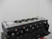
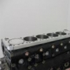
I made some progress today with the re-assembly of what is now an RB315. The rotating bottom end is now ready for a head and sump. I will hopefully be putting on the head and sump tomorrow, and with any luck starting the engine friday or saturday. A few pics of this build. The main differences between this build and the first prototype is that I am now using a standard head gasket, which has 3 benefits. 1, cheap, 2 seals better on a surface that will change with temperature differences, 3, handles big horsepower when o-ringed. These pistons are also different to the wisecos I used in the first engine. Im using CP's this time, and they are also thick crown flat tops so are suitable for the 22-24lb boost that will be required to make the engine deliver the 450kw goal I am after.
-
Good timing to ask that question as I picked up the last of the machined parts today, and tomorrow afternoon I'll be filing 24 piston rings and cleaning everything so re-assembly can start this weekend. All going well the new and larger RB315 will be back together again and running in a weeks time.
-
This is what your after. http://www.skylinesaustralia.com/forums/R3...es-t310996.html
-
My r34 at yesterday's track day. Had my ass handed to me by a pack of evo's. 6th in class D, out of 8 cars. If only having the prettiest car took seconds off your lap time....
-
Either way her words have helped push the ajenda of the popular media (organisations that call themselves NEWS that is). I hope Mark Scaife recognises the fine line he is walking here. Suggesting higher speed limits while at the same time as recommending a change in driver attitude and improved driver training allows those in opposition to stimulate public opinion to brand him as a "hoon". Once branded a hoon there will be little if anything at all he will be able to do to improve the situation on Australian roads. Focusing on one thing at a time will help, such as creating more awareness for the need for more driver training, and perhaps lobying the government to begin channeling a percentage of its road penaity income into such training endeavours. Focus on one issue at a time forces stories to be printed for what they are, and does not allow the media to take the reality of the facts out of context as much. I do wonder if Bev was read the whole story about what Mark had said, or if whe was getting a pedicure and a facial and was just asked to make a passing comment on Mark's suggestion to raise the speed limit. She could have easily been lead into making a comment that could be used to harm Mark's credability. Such a thing then printed serves to divide the motorsport community, further reducing the credability of anyone in motorsport that does speak up on road safety.
-
Not a bad idea. I was told that one of those morning shows did a recent poll regarding popularity of current politicians and an independant called Don Key was chosen to be more popular than current pollies. http://wagga.iprime.com.au/index.php/news/...d-abbott,411851 Thinking of licensing tests and their forcus on driver ability, it reminds me of how I got my license. Had to go for the test 3 times so I could pass. 1st test: Failed due to "driving with too much confidence", (I have been driving cars, go-carts and motorbikes since I was 12, doing all maner of stupid things and learning how to recover from such stupid driving activities). I also failed to make a right hand turn where instructed to do so (The test was on an unfamiliar winding road, and I had no idea where the right hand turn was so I didnt take it). 2nd test: Failed due to rolling over the painted line at an intersection at a Give way sign (which isnt against the rules anyway). 3rd test: Passed. Instructor had me drive him to the esplanade, wait in the car while went to buy lunch, and then drive him back to the QLD transport depot. No car control tests, no emergency braking tests, not even a hill start in all three tests.
-
Detailing The Trickly Spots On R34 Gtr's (badges & Glass)
GTRNUR replied to GTRNUR's topic in Exterior & Interior Styling
Thanks for the tip, autosol sounds like the go as its a little abrasive too. Funly enough after spending about 3 days polishing paint I cant rightly put the old badges back on the car as they dont look good enough. Going to have to buy some new ones, so that solves the adhesive issue at the same time. Cheers, Ian -
Who knows.. sticky valve that free's up when the temps get warm... but pressure testing it cold will identify the fault and allow you to fix it.
-
Best guess is that your BOV might be stuck open/faulty. You need to have the intake system pressure tested by a mechanic to determine where the leak is and precicely what is leaking. You might also find other leaks when doing this test so its well worthwhile having the test done. As for over boosting.. short of a gauge to verify what is really happening its anyones guess. For safety sake though you shouldnt be driving the car until its fixed. That is unless you also want to plan on blowing up and replacing the turbo. If it is overboosting, it will blow the ceramic wheel off the turbo pretty quickly. If it doesnt blow the turbo, then your risking detonation, lean running and blowing the engine instead.
-
I just got a set off ebay in the us. Arrived in 4 days too. http://cgi.ebay.com/ebaymotors/ws/eBayISAP...em=400111098540
-
Detailing The Trickly Spots On R34 Gtr's (badges & Glass)
GTRNUR replied to GTRNUR's topic in Exterior & Interior Styling
Thanks for the feedback guys. I think im going to go with the badge removal approach once I source some 3M tape. While using a tooth brush and a plastic screw driver on a rag got it a bit cleaner, but only complete removal is going to get it 100%. As for the glass, ive had good success doing the large area's with a wool polishing mop and a good cut and polish compound. I was thinking of trying a mini polishing mop on a die grinder to get into the corners, provided I can find one that is. I dont like the idea of acid too much. Sounds like a great way to start corrosion wherever I would accidenty spill it. -
I fitted my 18x9.5 +12 TE37's with 275/30 falkens last week to my R34 gtr. They do scrub, but only when there is extreme suspension travel with a little turning. For example when driving at a sharp angle out of a driveway to avoid scraping the front lip. In these situations the car is hung up on opposite wheels (left front and right rear, etc), and the tyre rubs the inner guard if you dont keep the wheels straight. (My car is lowered to 100mm and has 8+6Kg springs). With 19's you'd have more problems becuase the car will be lowered more to make it look right, unless you want it riding at 120mm off the ground. The scrubbing will also get worse too, especially if lowered. I was after 19's originally too until the 18's came along at the right price. Ive since learned that the 18's are the better option for handling anyway.
-
As Mike guessed I have quite an array of spreadsheets for calculating out all the geometry, etc. What started out as a couple of basic spreadsheets now calculate every aspect of the open deck engine. It was necessary so I could see what would work on paper before going out and needlessly wasting money. Yes ive heard of V8's using honda journel'd cranks as well, and they rev the hell out of them too. The reason they get away with this is that there is still sufficent main to big end journel overlap on the crankshaft to provide the crank with the necessary strength to survive. See Pic: The V8's in question are still running 5lt + in capacity but are able to do so by using 4" and larger cylinder bores. The stroke on the crank is usually either standard or even reduced. The smaller bearing diameter of the honda journel provides less rotational friction/drag between the rod bearing and the crankshaft. Honda have well proven their bearings to survive 10K+ RPM in race applicaitons. But in a V8 with a longer rod and a much heavier piston they have to use alloy rods to keep the stress loads on the bearings down. The other way around this issue is to custom grind a crank from billet material and use much larger main bearings. This has been done for years in the vw after market industry allowing up to 3lt 4 cylinders to be made using 90mm stroke cranks and 4" bores, and usually use a 50mm chevy size rod bearing. This might sound a little excessive, but it is actually being done more often than you might think. The Australian 4 cylinder all motor record holder made his own crank from scratch. He used massive ford clevland mains and chevy big ends to get a strong as hell 2.8lt 4 cylinder crank. I'd love to have 1/2 of his engineering skills. I think for 300kw, yes you would get away with honda journels, but in the end there isnt much benefit of going that way. The 300kw gtr recipe is very well known (GTSS's). Also, the honda version of the crank I made first was just an experiment. And while the SR20 rod version of the current/next version of the build will also work, I have since refined the design further and have a much better rod journel setup on 2 other cranks that works out to be cheaper and stronger. All this asside, the main priority is getting a spacer plate sealing system to work. And yes, copper or even a plain gasket would have worked far better than the MLS gasket. The reason I chose to use an MLS in the first engine was I took the advice of someone who had built similar engines, yet they hadnt seen my spacer plate design. It doesnt matter though becuase its all part of the learning experience. I didnt expect to get it 100% right on my first attempt. I doubt OS Giken managed to get it right on their first attempt as well. I am however expecting great things from the next build.
-
Well I couldnt help myself and did the calculations anyway. Its interesting looking at the numbers and how force increases with RPM and mass. Calculations assume the following data: RB26 rod weight - 473 grams SBC Chevy 6.25" rod weight - 643 grams RB26 Piston weight - 320 grams Standard RB26 Calculations Stroke - 73.7 mm Rod - 121.5 mm Ratio - 1.65 mm Acceleration @ 8000 rpm - 33.2 m/s^2 Acceleration @ 9000 rpm - 42.0 m/s^2 Acceleration @ 10K rpm - 51.8 m/s^2 Total Rod + Piston mass - 793 grams Rod loading @ 8000 rpm - 2346 gram force (26.33 newtons) Rod loading @ 9000 rpm - 3396 gram force (33.31 newtons) Rod loading @ 10K rpm - 4188 gram force (41.07 newtons) RB26 crank with 6.25" rod Calculations Stroke - 73.7 mm Rod - 158.75 mm Ratio - 2.15 mm Acceleration @ 8000 rpm - 31.4 m/s^2 Acceleration @ 9000 rpm - 39.7 m/s^2 Acceleration @ 10K rpm - 49.0 m/s^2 Total Rod + Piston mass - 963 grams Rod loading @ 8000 rpm - 3083 gram force (30.23 newtons) Rod loading @ 9000 rpm - 3898 gram force (38.23 newtons) Rod loading @ 10K rpm - 4811 gram force (47.19 newtons)
-
Interesting idea, though you would want to use aluminium or titanium rods if you went down that path. There is a point where the increased rod ratio (which lowers piston speeds and acceleration rates allowing a safer high rpm) is offset by the increased mass of the extra long rods. That increased mass combined with the intended higher RPM operation will up the load forces applied to the rod bearings considerably. If you were able to score some alloy chevy 6.25" rods cheap 2nd hand it might be worth a try. I can calculate out the piston acceleration rates for this setup if you want, and that combined with the mass of the rods will give you your bearing load forces.
-
Here's the other option to get the crank to clear the squirters and base of the cylinders. This is the first crank I made that is knife edged and modified to use honda RSX rods. This one is an 87mm stroke too.
-
Did the counterweights on the RB30 crank clear the block near the edges of the cylinders? They dont with an RB26 block, which might mean the 26 block has more material around and under the base of the cylinders to add more block rigidity. Getting around the squirters is easy, have a look at the pics of my crank and the photo with the squirter and how it fits the slots in the counterweights. Conventional I-beams are still square in the shaft of the rod. The pauter rods are at their narrowest where it matters (above the rod bolts). I think that 88mm is plenty large enough. At that stroke size it is hard to get a long enough rod in there to keep the rod ratio sane as well. 5.4 or 5.5" chevy length rods are the next way to go.
