

GTRNUR
-
Posts
1,970 -
Joined
-
Last visited
-
Feedback
100%
Content Type
Profiles
Forums
Events
Gallery
Media Demo
Store
Everything posted by GTRNUR
-
 Correct. The VCT valve works the same as an ignition coil or injector (no resistor pack to limit current though). +12V is always present on one side of the injector, and the activation requires just pulling to ground. The BUK456 mosfet is an N-channel fet. Gate is your +5v trigger with a 100 ohm input to limit activation current. Source connects to the solenoid grounding wire and the zener diode anode end, and the drain connects to chassis ground and the zener diode cathode end. Most RPM/frequency comparing circuits ive seen (that can then result in a boolean trigger) that used dip switches use the switches to turn on/use different RC circuits. Ie.... Time=Resistance*Capacitence. These circuits would switch in different RC combinations to a frequency comparitor IC. You can actually get all kinds of cool IC's developed to do just this sort of thing. Saves you having to design all your own circuits. The accuracy of these methods isnt necessarily very good though as component tolerances vary a fair bit. Entirely microprocessor is much more accurate. If you want to go entirely down the microprocessor path there is a far more accurate method of calculating RPM. A few years ago I made a whole efi computer. I developed a method of calculating RPM by using reciprical maths and counting micro seconds between ignition pulses. Basically I used an 8253 IC programed to operate as a micorsecond counter(uS not mS). Every igntion event it would stop the clock, read the counter of elapsed uS, reset the clock and start it again. The equation was something like this... RPM = 1/((timer count in uS+fudge factor constant to account for calculation and data aquistion time) * ignition pulses per 360 degrees ) The downside of this method was the processing overhead would also take a few micro seconds... thus the need to add a fudge factor. Even then it was extremely accurate as the calculation fudge factor is a constant, not variable. Once identified with bench testing it was a set and forget value. With the last version of my efi computer I did as much in hardware as was possible. I used 74LS373 IC's to operate as a buffer stage between analogue to digital hardware, and the 8354 timer. External triggering would trigger a circuit that would stop the counters, load the value into the 373 buffers, reset the counter, and start it again. The microprocessor could then read the values at their leisure, or when an interrupt was detected when a new value was loaded into the buffer that related to the 8253. I hope I havent geeked out too much here, but your a programmer with some hardware knowledge so Im sure you might find some of this useful.
 -
Faq: Apexi Powerfc - Frequently Asked Questions
GTRNUR replied to paulr33's topic in Tutorials / DIY / FAQ
I wasnt trying to make the ecu tunable by MAP sensor, I was just after logging and perhaps boost control on an L-jetro but using an after market map sensor. I ended up solving the problem with the calibration of the GM map sensor by coming up with a circuit to fudge the sensor output voltage to make it compatible with the FC. I did a post up on it in the forced induction performance section. I just realised it should have probably been posted here in Modifications/FAQ. http://www.skylinesaustralia.com/forums/Ad...Po-t313168.html -
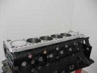
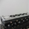
RB31DETT! Thats my project ! Here's the latest of my RB31. The engine is on a test rig and is ready to fire up. With the exception that I need to put dump pipes and an exhaust on it, and dynabolt the rig to the floor. Hopefully not longer than 2 weeks till I get that sorted out.
-
If your after some basic circuit idea's that might help the project... You can use a 741 op amp as a comparitor, allowing an adjustable reference voltage to be input with a POT (0-5V), compared to say an TPS input voltage, and the output of the IC will swing high or low. http://www.technologystudent.com/elec1/opamp3.htm As for driving the solenoid, using a BUK456 TO220 package mosfet with a 5 watt 60v zener diode setup reverse bias from the gate to ground is the easiest method ive found to switch big currents (up to 20amp). No heatsync required to. And the input of the mosfet just needs an input pulled high to 5V with a 100ohm resistor. Ive used these for driving fuel injectors and they work great. The zener is needed to stop the voltage spike the solenoid generates from cooking the mosfet. With RPM sensing, had you though of using an outside RPM detection method like an RPM activated switch such as Autometer/MSD sell? That way you can just change rpm pills to alter the activation RPM's of your circuit and the output is either high or low. Makes it a simple "no brainer" adjustment method. Good effort on having a go at this. Im with you in that there is a lot of satisfaction to be had from making something like this yourself. You'd be amazed what you can make when you start applying some of your trade knowledge to something you actually have passion about!
-
Disclaimer Starting off with the usual disclaimers, no guarantees, and of course im not responsible for your stuff ups etc. If you frequently burn yourself with a soldering iron then this isn’t for you. But if your capable of assembling a basic dick smith kit, then you can easily do this. Background So I initially wanted to add boost logging capability to my Power FC. Sure enough I happened to have a generic GM/Haltech 3 Bar map sensor in my stash of left over EFI parts from my various projects over the years. A little research and I found PaulR33’s Power FC FAQ/documentation on connecting the sensor to your FC so you can do the logging. Along with this information was the data for correcting the scale and offset when using sensors other than the common Apexi sensors. This was all well and good unless your Power FC doesn’t support the PIM Scale/Offset settings that need to be tweaked in order to make a non standard MAP sensor calibrated to the FC’s vac/boost scales. This was the case with the GM 3 bar sensor, so what I came up with is two circuits that can be used to correct the offset, or the scale and offset of the FC’s boost input. This allows the use of cheap and common sensors to interface properly for logging or boost control. (circuit diagrams are attached) Circuit 1 This circuit uses a 7805 (very cheap and common voltage regulation IC) and a 1N5004 diode (also cheap), to make a 5 volt regulated power supply for the MAP sensor. The diode is used to offset the sensor ground voltage by 0.6V, so that the inaccuracy is corrected. This calibrated the GM 3 Bar map sensor to the FC accurately, and presented an offset inaccuracy of 0.05kg/cm. The scales of the GM sensor and the normally used Apexi sensor must be pretty close (though I only tested to 1 bar). This cost me $1.90 in parts, plus the sensor and heat shrink I already had. I assembled the whole circuit mounted off the 7805 IC, and then wrapped the whole lot in heat shrink. The IC does not need to be mounted on a heat sync as the map sensor will not draw more than about 50-75mA. The circuit can do 150mA before the component needs the be thermally mounted. Circuit 2 This circuit is a variation on circuit 1, using a LM317T variable output IC. Same principal apples for offsetting the voltage, but a 2K carbon variable resistor is used to allow the voltage on the MAP sensor to be under or over driven. Under driving the sensor will allow the hand controller to display a lower boost level, over driving it, the opposite. EXTREME CARE MUST BE TAKEN IF YOU DO THIS… or you will let the smoke out of your map sensor, and potentially damage the FC map sensor input, or even toast your ECU completely. I would not over drive the sensor by more than 6v if it is an electronic type sensor (like the GM sensors). Also, take into consideration the boost levels you are running. Running to 1.5 bar on a 3 bar sensor means the output voltage of the sensor will be about 4 volts, and is still very safe for the ecu. Running the same boost level on a 5 bar sensor will have a much lower output voltage, as the sensors internal diaphram will me moving less for the given pressure. Also, running a 5 bar sensor if you only plan to run 1.5 bar is not a good idea, because while you can correct the scale and offset error with the circuits, the 5 bar sensor will give you less resolution (accuracy) than the 3 bar would. TESTING How the circuits work? Simple. The regulator IC’s provide a constant 5 volt (or corrected 5V for the LM317 circuit), with an offset ground signal. By using the 0.6 voltage drop or 0.3 voltage drop of common diodes you can offset the sensor’s output voltage. This corrected voltage is then used by the Power FC to produce and display the correct boost/vac levels. Using no diodes would be the same as running the sensor off the regulated power that is suppled from the MAP sensor plug on the ECU. Using a single BAT46 diode corrects by 0.3 volts. Using a single 1N5004 diode corrects by 0.6 volts. Running the diodes in series would correct by 0.9V etc… So this takes care of the input side of the boost control. Then you just need to score a 3 port solenoid for the output side. You can source these from anyone selling boost control solenoids in Australia. They are all the same. Haltech, vipec, wolf etc. Ive seen them being sold on ebay too very cheaply. Thanks to Paul and his FC manual for getting me started on this. Enjoy! Cheers, Ian
-
Im interested. Will you post to Cairns, QLD, 4870? If so get me a postage cost for at least the dumps, but also the front pipe unless "dori34" above wants them. CHeers, Ian
-
Faq: Apexi Powerfc - Frequently Asked Questions
GTRNUR replied to paulr33's topic in Tutorials / DIY / FAQ
Hi Paul, I've just attached a GM map sensor to my L-Jetro R34 GTR PFC and have discovered that there is no place to enter the new map sensor calibrations for the scale and offset. Is this a limitation of the R34 GTR PFC, or just an option that hasnt appeared yet in the datalogit software? Any suggestions? Cheers, Ian -
Ive had that before on my R33 gtr. I pressure tested the intake system and found that the leak was only under vacuum, and oddly it would seal up under a positive manifold pressure and hold a positive pressure once disconnected from the air compressor. I solved the problem by spraying the ends of the shafts with a little INOX a few times when it was idling. No disassembly required. A little of the lubricant will have been drawn in to wet the seal. This made the noise stop. It may have also made the seal swell a little too. That was over 3 years ago, and the seals are still holding. (I stil see and occasionally work on the car). The ideal approach would be to replace the seals and re-furb the throttles, or swap them with some from another car. Its a lucky guess as to weather you get a good throttle though. Getting the seals is the next issue. They cant be sourced from anywhere.
-
Wrecking R33 Gtr Vspec 84,000km Black
GTRNUR replied to BoostdR's topic in For Sale (Private Car Parts and Accessories)
Do you still have one of those 3" front pipes available? Are they 3" from the dumps to 3.5"? Im chasing a large front pipe system to suit my RB31 with tomei dumps. -
If your wondering about the thickness of typical 05u blocks, the last block i sleeved broke through on a couple of cylinders when bored to 92mm to fit the sleeves. The sleeve design was made to suit a maximum piston size of 87.5mm, allowing for a 2mm cylinder wall thickness which Dartron (sleeve manufacturer) consider to be safe for this kind of sleeved block. So what im saying is that if that same block had been used to run a 0.040" oversize piston the wall thickness at its thinnest point would have been just under 2mm. Thats not a lot considering the block is cast iron. Its no where near as strong as the spun cast sleeve material so that more or less explains why 87mm is considered maximum for most normal blocks.
-
Done! PM is on its way.
-
I need a Series ECR33 or R34 GTR coil pack loom. I am mostly after the connectors that fit the coil packs. Im not to concerned about the condition of it, so long as the plugs are intact. Cheers, Ian 0434 147 478
-
Coil Pack Differences. Series 1 & 2, R32/r33/r34 Gtr
GTRNUR replied to GTRNUR's topic in Engines & Forced Induction
Well that rules out R34 GTT looms. I was more interested in R32's and Series 1 R33 looms/coil packs though, as these are far more common and I can probably find a wreck a lot easier to pinch the plugs from if they are compatible. If anyone has a photo of an R32/series 1 coil pack and can post it up it will be helpful. -
Coil Pack Differences. Series 1 & 2, R32/r33/r34 Gtr
GTRNUR replied to GTRNUR's topic in Engines & Forced Induction
So you mean there is 3 different types of coil packs then? I only have R34 gtr coil packs in my posession. So these would be the same as series 2 ECR33 then I presume because im pretty sure they also use the SPF-005 coil packs...? -
Hi everyone, As I understand it... all R32's and the series 1 R33 and R33 GTR's use the same type of coil pack, which uses an ignitor module to fire the coils. And the series 2 R33's and all R34's use a coil pack that has a built in ignitor. Now here's the question.... Are the plugs for the series 1 and series 2 coil packs the same? The reason I ask is that I need to source a coil pack loom so I can cannibalise the plugs off it for a custom wire up that is using R34 GTR coil packs. I’d rather not buy a genuine coil pack loom only to chop it up for my project. Cheers, Ian
-
Locating A Plug For The Power Fc Map Sensor Port... Where?
GTRNUR replied to GTRNUR's topic in Engines & Forced Induction
I am after the 3 pin version of this plug. The pictures below are for the plug that is for PFC's that use the 5 pin boost controller harness. Its more of an general electronics grade connector than an automotive grade connector. -
Locating A Plug For The Power Fc Map Sensor Port... Where?
GTRNUR replied to GTRNUR's topic in Engines & Forced Induction
I dont want to use the boost controller kit for the FC. I just want to hook up a pressure sensor for data logging, so I need the plug that comes with the apexi map sensor. The apexi map sensor doesnt have the range of operation that I need, so im using a different sensor. Sourcing the plug is the problem, and buying a boost controller kit to get a 30 cent component isnt an option. -
Hi all, Im trying to locate a 3 pin female connector that plugs into the 3 pin port on the power fc ecu's to accomodate an external MAP sensor. Does anyone have an idea where I can source something that will fit? Ive tried pulling apart a few computers and power supplies, but have had no luck yet. Jaycar and DSE dont stock anythign that comes close to fitting either. Im beginning to think it will be easier to open up the ecu and solder on a diferent connector, or fit an external lead. Anyone have any suggestions before I do this? Cheers, Ian
-
Racepace Built R34 Gtr Nur Rb28 V-cam
GTRNUR replied to tangomatt's topic in Members Cars, Project Overhauls & Restorations
ARC do a tastey titanium brace as well. My next guess on Matt's mod list would be chassis bracing, unless its already done that is. -
Hi stuart, just tried to call you back to say stop looking. I think Ive found a loom locally. Cheers, Ian
-
R34 GT-Four RB26 Time Attack Build
GTRNUR replied to Luke_ENR34's topic in Members Cars, Project Overhauls & Restorations
Read my mind.Yes this is true... -
Getting a normal single throttle body is an expensive enough operation. I cant imagine what it would cost to have 6 throttles done at once. I think it might be easier to modify the base plate, weld and match port it to some aftermarket IDF/IDA/DRLA throttles. Injection Perfection does some really nice throttle with trumpets, which you could then build a custom plenum around. Ive seen then in 48, 50mm and larger. Extremely nice quality. The other options are to have the throttle shafts profiled, or change to these fancy looking things. http://www.gtr.co.uk/forum/106680-shaftles...s-rb26dett.html
-
Finishing Up Forged Cp Piston Rb30 Build, Few Q's
GTRNUR replied to jarrod83's topic in Engines & Forced Induction
Bolting the cradle on and torqueing to spec will have no effect on the cylinder shape. The bolts and supporting material are too far down the bore for it to matter, as well as the entire bottom area around the crank is heavily reenforced and has ribs etc (in a 26 it does at least). The only reason you want to go messing around with the cradle is if your using a cradle from another engine, if you have partially grout filled the block, or you are using ARP main studs in the block. About the coatings.... measure measure measure. Its fine and dandy to assume the coatings will be even and consistent on all pistons but you only get once chance to assemble the engine properly. Its not a big deal to measure up each piston to be sure. About the cooler temps and lower expansion rate due to that fact, it would be negledgable. I'd still be inclined to run them at the recommended factor clearances. The order I do things is: 1. Measure crank mains after having it machined and balanced etc. If using ARP main studs skip to 3. 2. install main bearings in cradle and block, install factory bolts and torque to spec. Measure for roundness and to determine overall clearance. 3. If out of round, then the cradle needs to be shaved 1-1.5 thou and then re-installed in the block and line bored. 4. If round but too loose, consider using the 1/2 thou undersize ACL bearings in either just the cradle, or in the cradle and block depending on how much clearance change you need. 5. crank with mains, and then install an old rod and piston in cylinder 1. measure deck, then repeat for cylinder 6 6. calculate the diference in angle level out the cylinders, and have the machine shop deck the block accordingly so all cylinders have the same CC. 7. Measure you pistons to make sure they are all ok, gudgens to. Then get your coatings done. Finally re measure them all and determine the largest diameter. 8. Add your desired clearance to that (2.75-3 thou?) then have the block honed to that diameter. I highly recommend either taking the engine to a place that can torque plate hone it, or try to borrow a plate from someone that can. You might have more success asking for an RB30 torque plate too. Hopefully I havent left anything out. I hope that helps. -
Thanks, that answers the question, and it seems I can source them from the top secret website.
