Search the Community
Showing results for tags 'c34'.
-
Alrighty guys so this guide/ build log/ r&d will outline how i installed the entire cruise control system from an a32 nissan maxima into my 2000 wgnc34 nissan stagea rsfours type b. So firstly I’ll just state I am just a 19 year old who has absolutely no qualifications, just an interest in electronics and car audio with, in the big scheme of things, not much experience at all. Take all of this information as just a guide and your own r&d as who knows, some of the things may even be considered dangerous! I do welcome feedback and questions though! Prerequisites and Warnings; If you can’t understand how to read, interpret and follow a proper Nissan wiring diagram I’d advise you not to attempt. You must be competent with a soldering iron and or crimping connections If you don’t know how to use all the functions of a standard multimeter do not attempt at all You will have to modify the clock spring, which houses the airbag wiring. This is a large risk that can result in airbag deployment if completed incorrectly then there is the obvious risk of fire/short circuit if any electrical connections are incorrect or poorly terminated etc/not fused i will not be wasting time showing you how to take your interior apart. if you cant workout how to remove your steering wheel/speedo cluster etc you probably dont have the ability to install cruise control into your stagea. Step 1 Wiring diagrams; The wiring greatly differs between automatic and manual vehicles, with the latter being far more simple as transmission control is not needed. It is probably possible with autos but I have not investigated if the transmission control systems share commonalities. I have included both so you can see the differences. Manual transmission Automatic transmission This series of diagrams --cruise control wiring diagram.pdf-- are the in depth wiring diagrams showing all factory pinouts, wire colours etc. they are just what a proper wiring diagrams are. within these diagrams there are various notes such as this one-- what i did was print out the full diagram and white out any unnecessary automatic parts of the diagram to simplify it. i also suggest taking note in this document ---how to read wiring diagrams.pdf---on how to properly read these wiring diagrams and most importantly for pinouts, understanding if a pinout is shown from terminal side or harness side. Step 2: What you will need A32 nissan maxima parts ascd control unit vacuum motor vacuum cable actuator ascd clutch switch ascd brake switch (looks the same as clutch switch, just take both switches on the brake pedal bracket and the clutch switch) ascd steering wheel switch ascd hold relay ascd main switch (can get a usdm d21 pathfinder switch i believe if you want the writing on it to be correct and not horizontal) note: cut off everything with any plugs etc included and give yourself as much loom behind it as possible (atleast 100mm or so), take all bolts/fasteners too take the clock spring and all the wiring inside the steering wheel becuase it comes in handy if you want to incorporate a dash light that says "cruise" take the maxima cluster and connectors too stagea parts you will need a steering wheel that has the large D shape side airbag bolt covers with brackets housed inside. i think series 1 wheels are like this but im not sure what models come like this. all i know is my rs4s wheel is smaller and doesnt have provisions for any audio control (left side) or cruise control (right side). second photo shows said bracket the throttle with second wheel bit (think this came on most autos but again not sure) parts you can get from any car the longest fattest section of wiring loom you can extract from a car (you could go try and find all the colours in maxima wiring diagrams, but i just used what i had and spliced the colours i had in between the maxima terminated ends. consumables and tools 6m of 7 or so mm split loom a heap of double wall heatshrink of assorted sizes electrical tape thats decent your usual pliers,flush cutters, crimping pliers, wire strippers solder and soldering iron pin removal tool and afew of them in different styles the most dangerous tool in the shop (stanley knife.utility knife) t50 torx socket t40 torx socket 17mm socket 10mm socket but seriously does anyone have any of these? phillips head screwdriver and tiny flatheads etc parrot clip leads for your multimeter (the spring loaded clamp ones that allow you to lock onto wires/pins) Step 3: modification (guess you could say fabrication) in this step il be showing you how i (poorly) mounted the ascd vacuum pump, actuator, modified the clock spring, modified the ascd controller case and modified the brake pedal. Clock spring the stock clock spring in my s2 rs4s type b has 3 wires in stock form, (steering wheel side) brown (batt12+), blue and yellow (airbag) The connector on the steering column side of the clock spring had 7 male pins as shown in this photo, (ignore the pen markings) so that got me thinking, if there is a 7 pin input to the ribbon cable there must be a way to add 4 more wires to the steering wheel side. see 7 copper pins through clear window in clock spring. i then peeled the sticker on the face back to reveal the clip that secures the steering wheel wires of the clock spring. to remove this cover the two plastic pins that appear quite butchered in the picture below (top and bottom) need to be cut down with a utility knife as they are melted down larger than the id of the covers holes to ensure if the two centre clips fail there is no chance the cover can come off. they need to be cut down so the "od" of the centre squashed pins are smaller than the "id" of the cover holes as shown in the picture. once the plastic "pins"were modified and free, the centre clip needs to be squashed together releasing the cover. the next picture shows the connection of steering wheel wires to the clock spring copper with cover removed (stock rs4s type b). you would probably find a tiptronic series 2 clock spring has 2 wires you could use for cruise control which means you may not have to perform these modifications. thats just a guess though, and i choose modifying my own over sourcing one to find out if thats the case. next, i cut the connector off the maxima clock spring show in picture below to add to the stagea clock spring. i removed these pins from the maxima connector with a custom pin removal tool that is inserted into the front and the plastic tabs were lifted up, releasing the pins out the back. the wires were then pushed through the stagea wire black sheath shown in picture below and roughly bent to where they would be soldered. (top 3 blue yellow green wires) i then realised there would be a spare pin available so i pushed a blue/orange wire through the airbag black sheath for any future use i think of. the wires insulation were then stripped about 4mm or so, and all were soldered onto the copper pads. (see blue/orange wire second from right). only 2 wires are needed for cruise control out of the 4 that i added total, but i happened to have the opportunity to buy a rare factory option steering wheel audio controller and knew this would require one additional wire, and planned to use that final blue/orange wire in some sort of a scramble high boost mode button configuration on the wheel, hence using all 4 wires. Important soldering tip: pre tin your wires and pre tin the pads. DO NOT put excessive heat into the copper pads at any time. this will melt the delicate ribbon connector attached to the other side ruining the clock spring for good. i did one at a time quickly (tinning helps this) allowing the copper to completely cool between wires. the base of the wires were then secured to the plastic with a small amount of 2 part epoxy. i then pushed the three pins (blue green yellow) into the stagea black connector with the brown wire (horn batt12v+) and there the blue orange wire is loose coming from the airbag connector wire sheath. i then checked continuity between steering wheel pins and rear of clock spring pins and ensured there were no shorts between wires, especially the airbag pins! once i new the modifications were successful, the wire cover was put back on. some material needed to be shaved off the inside to allow more room for the 4 extra wires. once it clipped into place with the centre clip, i used the soldering iron to slightly melt the plastic "pins" ensuring it would never come off, slightly similar to how it was secured from factory. thats it clock spring done! ascd vacuum pump and actuator All i did was mount the pump to the same bracket i had my catch can on in the back passenger side of the engine bay, and made a shitty bracket out of some steel and aluminium that i had lying around to mount the vacuum cable actuator to. this actuator is on the drivers side rear of the bay. im sure far more elegant nice mounts can be made up it works for me haha. ascd controller case (mounting) i mounted the ascd controller behind the drivers side kick panel on the relay bracket. first thing i did was remove one half of the ascd controllers case by bending out the pressed metal around it. once removed the outer metal case, i drilled out the 4 spot welds without going all the way through, removing the factory bracket. i then wire wheeled both the case and relay mount bracket and soldered the 2 together. the case was then put back together and edges bent back to secure it. the photo below shows the final product once completed. brake pedal in my rs4s there was only one weld in nut/captive nut whatever you call it on the brake pedal bracket for the stock brake switch. there is a second hold there but no weld in nut. there is also only one contact for the brake switch and no second one at all. for from my limited research i believe all autos come with both weld in nuts and both contacts ready to go (no modification necessary) (photo below shows view from behind with welded nut, contact and second hole with no nut) to modify; step 1 crack a bleed nipple on a calliper with a clear vinyl tube over it going up to a reservoir/drink bottle or something to collect brake fluid. this is necessary because you need to be able to push the pedal to the floor. step 2: push down pedal with your elbow or whatever and attempt to pry out that little rubber contact you can see in photo above. step 3: get yourself a bolt and nut ( i used a 16mm long m8 high tensile bolt and nut) and steel plate step 4: put bolt through steel plate (if the plate is less than 2mm thick you wont need to grind down bolt head) and push pedal down and put bolt through the hole where the rubber contact previously was and put nut on the back. align plate with the hole where the second brake switch will go and tighten nut and bolt with pedal pressed down.(first pic is side view showing bolt-2X1mm plate-pedal-nut) step 5: this step will make you want to give up. if you finish this you can finish the whole install. you will need a mate with a broom stick or some sort of long pokey device to push the pedal down while your upside down in the footwell. get the stock brake switch and a second nut in hand. get your friend to push the pedal down to the floor and get up in there and put the brake switch through the hole and try and thread the nut back onto the switch from behind. you will now have 2 nuts on the switch clamping it to the bracket. do not tighten down yet. step 6: adjust brake switch back and fourth, with your friend pushing pedal in when necessary, with both nuts so you achieve around 0-0.8mm gap between the switch housing and the contact. to see this you will need to get a phone camera up in there or something. step 5 and 6 definitely are the most difficult, curse inducing, hatred building, case of beer break worthy aspects of the whole cruise control install. step 7: put the brake interrupt switch in and adjust so there is 0-0.8mm of gap between the switch housing and the contact (now the bolt head) see photo below brake switch modifications complete! see photo below for photo Step 4: The wiring So you should have gathered a heap of body loom or wires of different colours from a wrecker/parts car already. ideally you want to use the same colour as the diagram but as long as you record what colours you use etc you should be fine. il tackle this section in the same way i did in mine, one page of the wiring diagram at a time. i will often refer to "running pin so and so to a given location" and in virtually all circumstances out of the car this wire run was a 1.5m or so extended length i had soldered in the colour i chose to the nissan maxima plug if that makes sense. where possible to simplify wire routing i grouped as many as i could in the one run of split loom and when i new i would have afew wires going to the same location i used a drill to for twisted pairs or a larger twisted loom. i ran 3 main "runs" of split loom, one to the main switch, one to the clock spring and any brake switches and a third into the engine bay for the ascd vacuum pump. i suggest soldering extended lengths of wire for all "runs" to the plugs/pins you will add such as brake switches, clock spring connector etc, then running these wires through split loom so they all end up at the ascd controller area and final soldering is consolidated to one location after all other connections are finished. Page 1 of wiring diagram (EL-145 main switch) and page 5 of wiring diagram (el-149)/ "run 1" of split loom so this page for the manual transmission diagram only has just the main switch wiring and ascd hold relay. first wire: pin 1 of the ascd main switch. this is ign power and it is the same source as the ign power for the ascd hold relay. what i did is i found luckily in my scrap wiring loom, a pin that is the same as the pins on the interior fuse panel connector. i chose to do this as factory as possible so i pulled out the fuse panel, bridged the ign relay and traced out 10A fuse that isnt used with the continuity function and found the ign output pin for this fuse. the first photo shows that bottom row, 3 from left (white out indicator) pin will give you 12v+ ign through the red fuse in photo 2 with the white out on it (bottom row 2 from far left) to add the female pin to the harness side connector i sourced the same pin out of the scrap loom i had which looks like the photo below. according to the wiring diagram this wire runs to the main switch (which goes rhs of steering wheel next to fog light switch in speedo cluster surround) and also the ascd main switch (mounted on the ascd controller relay bracket) so i ran the wire off the pin back down the loom towards the mass of wires inside the upper part of kick panel (as a sub loom) then, as i earlier spliced a second wire into the long length (made a y split), i ran one side down to where the ascd relay mounts and one forward out the dash where the ascd switch goes. just incase your connector falls apart like mine did (dont fully take out the inner pin securing backing plastic on connector, i learnt the hard way) here is the wire colours and placement on the connector. the pink/blue wire is the pin i added that connects to third from left as referred to before and the fuse. now pin 4 and 6 of the main switch are both just grounds (pin 6 shows it goes to el-ill or the speedo cluster but upon further investigation its just a ground). i soldered pin 4 wire to pin 6 wire 100mm or so down from the connector and then ran the ground wire right down to where the ascd relay is (same run as the 12v ign+ pin 1 wire). pin 2 and 3 wires were ran down to where the ascd relay is and pin 5 wire was ran 150mm or so down the run of wires then came out of the loom as it were to go to the speedo cluster. now page 5 (el-149) shows pin 7 (speed sensor) and pin 13 (cruise lamp indicator) both go to the combination metre (speedo cluster) so i ran these lengths of wire up the same split loom as the ascd main switch wires, and had them come out in the same spot as the pin 5 of the switch to form a sub loom that heads towards the cluster. (photo below shows 3 speedo sub loom wires before i moved them 150mm down the loom for neater routing. a thicker gauge ground wire with ring terminal crimped and soldered to the end is then thread up "run 1" from the ascd relay area up to where the "Y" is that goes off in the sub loom to the fuse panel connector. this ring terminal is bolted to the common ground thats really obvious just above the large opening in the kick panel metal. pin 2 of the ascd hold relay is crimped and soldered with the ground (pin 4 of the ascd main switch), and pin 3 of the ascd controller to the other end of the thicker ground (down at the ascd relay to form one large common ground for everything. so this "run 1" loom, from ascd main switch to ascd hold relay/ascd controller" has all 6 wires from the switch, a ground and the ign 12v+ fuse panel wire thats splits off in the middle , then 3 split off to the speedo (pin 7 of controller speed sensor, pin 13 of controller cruise lamp, and pin 5 of the main switch the illumination). Page 1 (EL-145),2 (EL-146),3 (EL-147) or "Run 2" of split loom this will be split into 2 sections, brake switch interrupts and clock spring connector. all wires in this section run down the same loom Brake switches so following on from the first section or "run 1" of loom, pin 2 of the ascd main switch on diagram EL-145 when you simplify it, ties into pin 3 of the ascd hold relay, pin 4 of the ascd controller and also then goes off to pin 1 of the ascd clutch switch. what i did here is i connected all 4 wires together in one location down where the ascd hold relay/ascd controller is. the photo below shows run 1 coming in and hidden under heatshrink and tape this 4 way junction takes place and the green/black wire thats visible is now going off in run 2 towards the clutch switch. also in "run 2" a length of wire is ran from the ascd controller area to the brake switch area to connect to pin 5 of the controller and pin 2 of the brake switch. another run of wire is ran from the ascd controller area to the brake switch area through "run 2" split loom to connect to pin 11 of the ascd controller and splice into the factory brake pedal pin 1 (this is the stop lamp switch, sends +12v to the ascd controller when pressed like your brake light) thats it for the brake switch part. will continue the next sections in more comments as this is way too long for poor old sau and its lagging heavily (probably my crappy late 2011 macbook pro)
-
From the album: Vic road trip 2005
-
From the album: Arctopus album
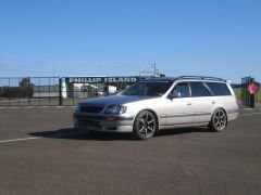
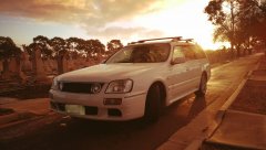
Its hard to find original locations to take pictures in. -
Hi ther, i have a problem that came after i changed my baulbes in my AC, replaced them with LED's and my cluster started messing up, Fule and Engien heat is always on max, spedo don't work, and RPM bounces on 500-1000rpm on idel and under full pupp it only goes up to 3000rpm, and the KM on the car reads 999999. Changed back to my normal baulbes and cheked the wiers to chek if ther was any faulty wiers behind the AC unit but coudent finde anything, changed back to my old Baulbes and it stil dosent work. I alsow blew the fuse for "Tail L" wile replacing the baulbes and have replaced the fuse. So, what can be the problem? Can i have messed up the cluster and blew a resistor? is ther a relay that have exploded? I have had the AC unit and CD player out 6-7 times and tried to turn the key on and off, and sometimes it works like it shoud somtiems it just a bit faulty shoing way to hige RPM and the wrong KM (shows about 116k the car has traveld 160k) Sorry if the post is messy, im not always that good at explaning things
-
Stagea C34 Series 2 $8k or swaps for something of interest of equal value: - Canon Camera gear - I already have a 7D MKII so more after professional lens, 5D MK IV/1DX MKII bodies and additional items to meet value - Aviation related stuff - Car parts - turbos, wheels etc. to suit R34 GTT - R34 GTT M/T (damaged or non damaged, as long as it runs/drives and not mangled) Not interested in other cars that are "made to be modified"/sport/track/performance cars. Perhaps a luxury daily or late model "normal" car is considerable. !!!PLEASE PM ALL MESSAGES REGARDING OFFERS/SWAPS!!! 1998 Stagea Series 2 C34 - MLSR Head gasket - ARP Headstuds - Full reconditioned head with less than 2000 KMs - Alloy Radiator - Braided Brake Lines - Upgraded R34 GTT Brakes all around (4 piston front, 2 piston rear per calipers) - Bottom end inspected and checked with no issues - High Flow Turbo - BC Racing Coilovers - Heavy Duty Tow Bar - Used to tow cars - Twin Sunroof - Works Wheels (nothing decent) - Nismo Exhaust - Alarm & Immobilizer System Photos will come later as I'm away from the car at the time of posting this. !!!PLEASE PM ALL MESSAGES REGARDING OFFERS/SWAPS!!!
-
Hi all, So basically my Series 1 C34 stag was stolen and I was lucky enough to get it back! When I got it back I noticed my Xanavi system won't turn on at all BUT my climate control is working and seems to be permanently stuck on auto (my xanavi system houses my climate control so there's no way to turn it off without getting the xanavi to turn on). Before I go spend some cash on an auto elec to diagnose/ fix, just wondering if anyone's had this issue before or would have an idea of what my problem could be so I could have a more educated look myself? Would the thief unplug something when stealing the car? unlucky timing with fuses? Extra info; Cigarette/ 12v power still works my gearshift lights (P R N D 2 1) turn on from time to time but very occasional - worked perfectly before the light for my "power/ snow" switch still works when in power mode when I got it back my centre console was popped open (assuming it was done when stealing) Any help would be appreciated, Cheers, Nick.
-
Hi everyone, I need to get the key barrel repaired on my s1, has anyone else pulled theirs out and would they have any advice? in doing searches i can find loose instructions for r34 but not c34, is it the same? thanks in advance keni
-
Hello everyone, I've got 96 Stagea (RS Four). Some days car works perfectly fine, others it becomes jerky straight away after start without 4wd light coming on. When the 4wd light comes on it reads as code 54 (Pressure switch and circuit). Car gets very jerky at low speed, especially if turning. If I turn the engine off and back on it erases the 4wd error and car works fine. Fluid for 4wd system is at adequate level. MAF had been replaced. I'm just wondering if anyone had the same problem or you guys know what might be the issue. P.S. Please forgive me if I sound silly as English is not my first language.
-
as above can anyone help me with the ecu pinout. it works in the car just does not communicate with the autobox so I think some pinouts are different
-
Have for sale my daily Nissan Stagea: Auto, leather seats, tinted windows,smoked tail lights, jap rims, massive wing, cd player and speakers,put in coilovers 6 months ago, pod filter, safc, front & rear sway bars rego till july, 202kms on the clock, side skirts(not on the car) old owner did a full respray on car overal in average condition car comes with a few spare parts $8,000ono 0.4.2.4 7.1.0 9.8.8
-
So, I've recently purchased a C34 Stagea with the legendary RB25DET engine. It was brought to my attention that I cant drive a turbocharged car on my green P's. I was un-aware of this because im from NZ and there were no restrictions on engine size there so it never crossed my mind. I'm also on green p's only because I am under 20 I transfered my New Zealand full licence and have my green P's until I'm twenty in January. So anyway I came to discover that I can get an exemption since it's power to weight ratio is under the limit. I went onto the raws website and screenshotted and printed off the details of the car, weight and engine power output. took it into the department of transport and they said they couldn't use it and that I need a letter from nissan stating the weight and power output. I emailed nissan Australia and Nissan Japan and they both said they couldn't help thats when i found the raws website but apparently that's un-usable, completely wasted my time waiting at the department of transport for nothing which is always fun... If anyone could help it would be greatly appreciated! Dont wanna go selling it straight after buying it. Thanks!
-
Hi ther, Seams like my Stagea rear diff have sailed of to the limbo betwhen life and death, and want to know what i can put in it? Frome som reacerch the Stagea have an R200 diff, witch means ALOT of funn options! But i alsow know i need the same rations as the one i have. I want to put in an LSD in it, and wondering if im gonna get my hands on a s13 or s14 LSD because they are easy to obtain and can handel the driving i do with the car. But then i wonder, if i just change the intestens of the diff, and leav the pinjong wheels from my existing diff, wil i have the same ratio as i have now? im not to edjucated in this, and googel havent given me any good answers! And to somthing in the completly diffrent end of hte car! I got myself a set of rb26dett Coils, because i found out that rb25det s2 and rb26dett coils was supose to fit, BUT, the conektors are diffrent, and wondering, can i just repin the original wiering with new rb26dett conektors? Or is ther anything more i need to think about? Hope somone can clearefy a few things for me!
-
Two are up for sale,both in good working order Pickups from Mt.Gravatt/Brisbane Can drop them off locally or send registered mail PM to contact -1998 r34 gtt starter motor from series two NEO rb25det $70 ono -1999 rs4s AWD Stagea starter motor also from series two NEO rb25det $70 ono
-
Hey guys and girls... got an ad on gumtree if you cbf looking it up. Located NOR Perth, WA Got some random left over parts that came from a silver c34 series 1 stagea. heres a list: Super stupidly rare grille (Series 1) - I think it is off a 25G and there were stuff all of those imported and its the only one in Perth that I am aware of. $250 Silver rear bumper (series 1) - $100 R34 silver bov piping (connects to black pipe which connects to BOV) - $10 3 rear baby seat clips (on roof cargo bay area) middle clip cover snapped off on one (would suit someone who needs one or 2 covers?) grey in colour - $10 Supa cheap red pod filters (have one that was used for 2000kms and another that was on the car b4 i bought it so pretty old and little bit faded) - Good one $15 , old one $5 Also have set of shocks/springs combo I bought off someone over east on SAU - told me had done 110000kms and I used for maybe 10000kms or so (was told it had lowered rear springs but pretty sure they are stock height but fronts def lower) - It has stock front shocks with rsr springs and rear kyb agx damper adjustable shock with stock springs - $250 Front driver seat - $50 4 contipro sport tyres (235/45/17) - good for skids/drift around 2-4mm tread ($50 set) Prefer txt message (0422 194 26four) or email (peter-toth@hotmaildotcom) as I don't go on here anymore (ONLY ABOVE ITEMS ARE STILL AVAILABLE) can send new pics upon request. I am open to offers on everything EXCEPT the grille as that will remain at $250 until someone is prepared to pay what I am asking as its worth it Cheers yo! Peter
-
had a quick browse and didn't see this one covered before just wondering if anyone can clear up weather of not a set of coil overs from a 25rs stagea will fit an autech stagea ?? as far as i know autech's are fitted with straight GTR components on their suspension??, but just no sure if the same goes for the 25 rs's. cheers.
- 1 reply
-
- stagea
- suspension
-
(and 3 more)
Tagged with:
-
Hey just wondering if anyone can confirm whether or not this is a genuine blitz nur exhaust or not has a jasma plate underneath the cannon Cheers Darren
-
So this is what my car looked like the day I bought it, complete with Dolphin body kit Yep nice and clean, note the ACT plates (you guys have lovely roads). Well this was very short-lived, after introducing the Stagea to the 'fantastic' roads we have to offer in NSW it wasn't long until it was copping a few bumps and scrapes. Then one dark night a chopped up drum of some kind was left in the middle of the road in an 80km/h zone which fatefully met with my front bumper causing much damage and distress. It wasn't a good look, but I didn't want to spend the time and money fixing it with the thought that somewhere down the track it might happen again. So I thought why not clean it up and create a custom front bumper! I was forced to drive around for about a week without a front bumper since I was having problems with my forester... and somehow escaping the glares of about 6 cop cars we made it without incident and re-attached the bumper today! I've grown fond of the look (although my black FM Intercooler is now a bit visible), what does SAU think?
-
Hey guys, I through this in the stagea discussion thread initially... Looking to get a new car and thinking of offloading the Stag. It's a Black 1999 series 2 C34 RS V (rear wheel drive). Dayz front and rear bumpers. 123,000kms. Great condition inside and out. I had to replace the turbo some time ago which I did with a Garret ball bearing type of a similar size to original, apart from that and it being lowered (RSR springs - previous owner) and mags, it's unmodified. I've kept it serviced every 5000-7000kms and have had no major dramas. It is a great car and I will be sad to see her go, just looking for something a bit newer. Before throwing it on car sales with the other 85 stags that have been on there for donkey's, I thought I would throw it out on here to see if anyone's interested. Being an RS V rear wheel drive, black and generally unmodified, it makes it a tad rarer I guess and could be a good project car for someone looking to modify from a fresh start. It's never been dinged apart from a rear bumper on a gutter incident my girlfriend claims no knowledge of which has been repaired with the same bumper perfectly. I'm throwing it out for $10,000 NEGOTIABLE. Pics attached, I have more upon request. As I'm sure you've gathered, I ain't the biggest mechanically techy kind of guy, but I'll answer any questions I can. I'm based in Brisbane. Cheers, Dan Jacobson incursion4@gmail.com 0414 509 159
-
Hello SAU, I've been using the forums for awhile now to find useful information - so thanks in advance! Today I've finally joined and the reason for my first post is to call out for help in identifying the rear lip as shown below. I have been searching around for a replacement, but haven't been able to find the same one. Alternatives are available (such as DAYZ or full rear bar update), but seem to take the styling a little too far for my liking. Any help would be appreciated.
-
2001 Nissan Stagea C34 RS4S Location - Woodcroft South Australia Contact - 0404 556 480 Regretful sale, no swaps! Owned by a mechanical business; very well looked after and maintained. Most of the mods (including the Nistune) were done in Oct/Nov 2013 before our last NSW trip. - NEO RB25DET - 5 speed Factory manual - AWD - Metallic Silver - 2500KG heavy duty tow bar + new Hayman & Reese surround - Roof racks (currently not fitted) - Factory wind protectors - Just Jap stealth black front mount intercooler kit (new) - K&N panel air filter element - HKS ABFLUG Coilovers (front) – Tein Coilovers (Rear) - Hardrace adjustable rose jointed R33 GTR castor rods (new) - Adjustable rear rose jointed control arms (new) - Custom brake master cylinder stopper (new) - Nistune making 170KW at all 4 wheels on 12psi + dyno sheets (recently tuned at Classic Performance) - Oxygen sensor (new) - Spitfire coil packs (new) - Walbro fuel pump (genuine new) - Just Jap stainless steel 3 inch dump/front pipe (new) - JJP High flow cat converter (new) - Custom 3 inch cat back exhaust with anti-drone rear muffler (Exhaust by Classic Performance) - Alloy radiator (new) - Front and rear QFM A1RM brake pads - Turbosmart boost controller - Intake hard pipe mod - Genuine Nissan front strut brace - HID head lights 5000k (new) - LED front parkers, rear number plate and cabin lights (new) - Steering rack spacers (new) - Modified steering knuckles - Flushed brake system with Nulon Super DOT 4 fluid - NGK Spark plugs (new) - Steering rack ends (new) - Tie rod ends (new) - Front and rear diff oils (new) - Transfer case oil (new) - Nulon fully syn gearbox performance oil (new) - Coolant with super long life (new) - Aftermarket gear knob - Upgraded front & rear speakers + mp3 CD player Done at 100,000KM the following: (approx 11 months ago, all the Ks since have been highway ks) - Genuine Nissan timing belt - Genuine Nissan tensioner - Genuine Nissan idler - Genuine Nissan camshaft seals - Genuine Nissan crankshaft seal - Genuine Nissan rocker cover gaskets and half moons - Genuine Nissan gear stick boot - Genuine Nissan water pump - Genuine Nissan sway bar bushes and links General Specs Tinted windows (legal) ABS Traction control Airbags (driver & passenger) Airconditioning Electric windows Electric mirrors Central locking 12v socket in the boot Fold down back seats Space saver spare tyre We have always used Nulon fully synthetic oils and genuine Nissan oil filters every 5000km. We have towed to NSW twice with a car & trailer on the back with absolutely no mechanical issues. With the coilovers/upgraded suspension bits, the car did not sway with the trailer on the back (even at 110kms) and sat very evenly. There will be more that we have forgotten to mention, if interested please come and inspect. Mechanical inspections encouraged and very welcome. Will come with 3 months fresh registration. RIM & TYRE OPTION With factory/stock R34 rims & Federal Evo tyres - $12,900 With R34 GTR Rims & Achilles ATR Sports tyres - $14,000 (we would rather sell it at the cheaper ^ option) OPEN TO REASONABLE OFFERS – In no hurry to sell. (No time wasters)
-
I have now sold both my skyline and stagea and about to move house, so time for a garage sale... get on it! R34GTT wheels painted black Bridgestone Potenza S001 tires $700 good condition 225/45/17 R34 GT/GTT aftermarket front bar $100 fiberglass with vents both sides. painted black, some scrapes and marks mostly on the underside where it is not visible. larger opening and shallow cut for FMIC, selling cheap cos its not coming with me. RB25-DET NEO genuine coilpacks $100 one is weak and caused a slight misfire. selling the full set of 6 but only expect to use 5 i dont know which one was missing, great for replacing one or a few faulty packs on your R34 or C34 with NEO RB26DET R32 GTR genuine coilpacks $200 excellent condition genuine items no missfires very minimal Kms, these were replaced with splitfires which felt no better to the genuine items. can be used on RB20s as a good upgrade as i did on my 32 R34 GTR dash $200 unknown KMS but i have been told it should read about 28000km from the previous expected owner awesome condition, cannot fault. can be used in a GTT, great for manual conversion R34GTT RB25 Manual Tailshaft $200 to suit coupe great condition good unis. open to offers but unlikley to ship R34GTT stock exhaust (cat to rear muffler) $100 great condition, great for trips to regency (doesn't include the rear tips) C34 RS4S stock exhaust $100 great condition, great for trips to regency comes off an AWD
-
Hi all, Need to clear some parts, most parts are located in Cronulla NSW unless noted. Happy to post at cost. Brand new LS1 coil packs, with leads and bracket to suit, coils sit on the inlet cam cover/injector wiring cover. $500 R33 Series 2 steering wheel, good nick, complete with airbag, red stitching $150 R33 GTR rear Carbon Fibre wing insert. $300 Brand new GTX2863 x 2, can include rear housings to suit $2400 Used HKS GT2530 x 2 including actuators, missing a few studs, bit of shaft play nothing major. $1800 Stagea C34 Auto coilovers, used, unknown spec $400 R33 GTR ARC airbox, used filters are near new, missing metal retainer, $300 R33 GTR bonnet, used, $350 (located at Parramatta) Damaged R33 GTR genuine front bar, as pictured $100 (located at Parramatta) 1000cc Bosch injectors Sold pending $ C34 Series 1 Days Side skirts & rear skirt complete with brackets $180 C34 Series 2 taillights full set $150 PM me if interested,
-
Chasing a set of C34 stagea coilovers for my S1 RS4 auto stagea. inbox please.

