

Announcements
-
Similar Content
-
-
Latest Posts
-
 Sorry had a bit of a week and haven't had heaps of time to follow this, so apologies if I've missed something - any chance of showing a log with the rpm, turbo speed, MAP, and wgdc all in one view? Definitely an "interesting" problem, and while it's definitely worth noting that there was a similar issue with the twins I'd not completely put all bets on the root cause being the same thing. Keep an open mind, follow the data.
 -
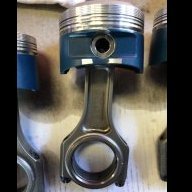
 I built this engine approximately 12 years ago so my own head (brain) is a little grey on the exact hardware in the RB head, however what I recall is. Stock RB25 NEO TURBO Intake Camshaft HKS 260 degree Exhaust Camshaft (R34 GTR) RB25 NEO Turbo Springs I ported/removed the exhaust stud humps found in the RB25 head so theres less turbulence but it wasn't ported/polished properly, just a hump removal. I've attached two pictures of the before and after to illustrate. The ECU gets its boost reference from the nipple on the rear of the head on the intake side, behind the fuel rail. The wastegate gets its boost reference from a nipple on the cooler pipe immediately after the comp cover. Could a decent pressure drop across the intercooler cause the wastegate to be seeing a higher PSI than what the ECU is seeing, and thus it can't control it accurately and quick enough? We ran a line to the actuator and watched it open and close using an air compressor, while we didn't have a gauge on the line to see when it was cracking open, it was opening smoothly. I just removed the gate now and even though the documentation says you need to open it in a vice due to preload (which I did), there wasn't any preload on the cap, which is something we noticed straight out of the box as well when new. This silver cap internally is threaded to the actuator rod that runs out the bottom of the straightgate. Not sure how I'm supposed to get this spring out to be frank.. Potentially but everyone else doesn't appear to have to stop at 500kw because of 6boosts design. I would, but I think I'm getting to that point where if I'm going to do the head and make another 100kw, then I'm going to need a fancy gearbox and quite a few other things and 10k becomes 20k becomes 30k within a few months. I'm not necessarily sold on the idea just yet that the head is restrictive at 4000rpm (and what.. 300kw?) and yet doesn't seem to be restrictive at 7000rpm when it's making 500kw, however I'm obviously not closing the door on that theory.
 -
 Yeah - Half the problem is I know this sensor actually goes to 150C.. I'm pretty certain it is min of 11C. So still more data required I suppose. It's really quite hard to get the oil temp to 100+ then immediately pull over and take a reading before the temp drops. Annoyingly I suppose the range I really 'want' is likely 80 -> 120C. TBH the ecu can't really *do* anything with it, and the gauge itself is very visible... ...but you know how it is.
 -
 My EFR 8474 Black, made 800awhp on a roller dyno. at 25-26psi. E85. Shaft speed was around 106,000rpm 1.01 rear. The rear is maxed. 6 boost Turbosmart 60mm gate 3.5inch exhaust Head is worked to the shithouse. Bain racing. VCam. 272 exhaust. RB28 - RB26 foundation. You have an intake issue. Start getting proper data and I mean go back to the simple things. - Pressure test your intake - Block off the Turbo BOV, you don't need it. - Test pressure before and after your intercooler If your head is pretty stock, that is your issue. Especially if it is NA. Take it off and spend $10k on it.
 -
 Temp = -21.052 X Voltage + 114 That should get you pretty close. Calcs based on two points I could do easy calcs on (30 and 70 degrees). It also says your sensor should only read as low as 9 degrees when it maxes out at 5V, and should hit a peak of 114 degrees at 0V... Just as a heads up if you were going really cold places, or wanting to be aware when temps really go up with it.
-


Recommended Posts
Create an account or sign in to comment
You need to be a member in order to leave a comment
Create an account
Sign up for a new account in our community. It's easy!
Register a new accountSign in
Already have an account? Sign in here.
Sign In Now