
Compression Ratio, Load Point, Ignition Timing, Injector Duty?

Announcements
-
Similar Content
-
-
Latest Posts
-

By Chocolate Cheesecake. · Posted
I recently purchased a 2018 Infiniti Q60, which has an SD card navigation map. I can see my system has options for real time traffic updates etc, and am wondering if there is something I can purchase to get this working? I can see there are at least updated maps for USA and Canada, but nothing for Australia. Surely Infiniti took changing road systems and city expansions into account when they decided to use an inbuilt navigation over Android Auto/Apple Car Play, or are we doomed to drive on streets that don't exist in the navigation system if you drive to a new area? -
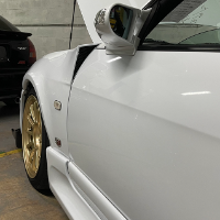
 Luckily I didn't put in etch primer as I just found out it's not compatible with my body filler lol. Also just need to sand the panel anywhere between 150-400 grit so I'm in the clear there. It does say to not apply to soft old paint, I assume that means paint that is flaking, peeling,etc
 -
Yep will do, thanks for all the help.
-
By itsforandres · Posted
@dbm7 and @GTSBoy thank you both very much! will give that a shot! -

By Murray_Calavera · Posted
Sounds good. Provided the panel is flat/level I'd be happy to start the painting process. While you are learning, for sure you could do this. Its only paint, you can always sand it all back and start again. Its only your time and money on materials, but while you're learning, really its time and money spent on your education. Once you know how to do this bodywork and painting, you won't want to waste your time and money on frivolous activities lol.
-


Recommended Posts
Create an account or sign in to comment
You need to be a member in order to leave a comment
Create an account
Sign up for a new account in our community. It's easy!
Register a new accountSign in
Already have an account? Sign in here.
Sign In Now