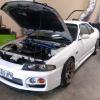
What Cams To Use In Rb30/rb25de Conversion?
Announcements
-
Similar Content
-
Latest Posts
-
By joshuaho96 · Posted
If you really don't want to touch anything you can try to trigger off the timing loop just to see if it's sparking semi-regularly. Don't trust it for actual timing measurements. -
Hey everyone, I have a r34 GTT s1, im having a problem with my skyline, ive let the car sit in the garage for the last couple of months and havent run it and ive gone to fire her up today and it cranks but doesnt fire, i have been having problems with it previously where it wouldnt start again after driving it around for a bit. It use to start fine on cold start ups but if you drove to the petrol station and fueled it up and went to go start it again, it would just crank and not fire untill you let it rest for a few hours, the car doesn't over heat it sits perfectly in the middle while driving when warmed up. Im thinking this problem has caught up maybe and now it just wont start at all. The car runs on e85, ive checked the e85 seems to be fine. I can hear the fuel priming before you go to start it and checked all my fuses and relays. List of things I replaced today - New battery - New sparkplugs - New Coolant temp sensor I was thinking about testing the CAS but from what ive seen online, if the CAS is cooked, the car will actually start up but then die instantly? as mine just doesn't fire at all. Does anyone have any idea or have encountered the same problems? thanks
-
Modern reg stuff now, they'd have a wide input range which would push through a buck converter, it would need to be able to maintain voltage for cranking conditions (sub 9V at times). Likely runs something like an internal 6V rail, and then further voltage regulators depending on which circuit/area it is feeding. Modern voltage regs, like what I'm starting a new power supply design with at work, will let me run a 5V rail output, and as long as my input is equal to or greater than 5V, I have a 5V output. Except I'm not pushing a 5V rail in our system as I don't need one, we're setting up for a 3.8V rail. Our new design will allow me 6 to 60VDC input, and everything else doesn't care, even when I start pushing a few Amp outputs. Realistically, the voltage drop off could be caused by a few things though, one could be literally the alternator is dieing, and hence charge power is dropping, which also means on a straight hard pull you're starting to send the battery flat... (Not that likely from a single couple of gear pull if the battery was fully charged). However, having earth issues, like stray earths not connected, or someone having put a ground loop in, will see the ECU appear to end up with lower voltage "input", mainly because the "ground" is no longer equivalent to battery negative. If they're comparing the input voltage using sensory ground for example, and sensor ground is what is in that ground loop, than the sensor output voltage will actually start to be reduced, when compared to battery ground... Yeah, ground wiring design can start to be a bitch... Also voltage going weird from inductive loads not being managed properly is another real bitch... Hence, why I asked above about how everything was wired in. If OP knows, and can post all of the actual connections from the ECU pin out, as well as what wires are joined where in the loom, which grounds from the ECU have ground points and where they are etc. Would help to see if there is a ground issue. The part I'd start with though, is putting a mechanical oil pressure gauge on to confirm the theory. Otherwise the next track day when the threshold is lowered could result in another of @Duncan favourite types of jokes... Knock knocks... Pretty sure this is what @GTSBoy is also self high fiving... Is all great that we have a decent theory... But they need to prove it before relying on it...
-
When I worked at BlueScope Steel, we had an Ethernet network, with every switch setup with a duplicate switch. Even when looking at all the primary switches, they had duplicate links, there was then also duplicated links between the primary in section A, to the duplicate in section B. So for each location that had networking, there was 8 network links. This was all back around 2007. That setup caused sooooo many issues, as many of those links were fibre. The network guys ran everything with Spanning Tree Protocol. And then we had great joy... The FOC Transceivers were slowly dieing, but in an intermittent way. And a lot of the time as they started to die, they'd drop offline for about 30 seconds... Spanning Tree Protocol was requiring 45 seconds to "rewire" the network... And by the time it was mostly finished, it had to start again as the transceiver was back online... Queue entire production network being constantly spammed with the spanning tree protocol messages... My god I do NOT miss working in huge environments like that!
-


Recommended Posts
Create an account or sign in to comment
You need to be a member in order to leave a comment
Create an account
Sign up for a new account in our community. It's easy!
Register a new accountSign in
Already have an account? Sign in here.
Sign In Now