

Announcements
-
Similar Content
-
-
Latest Posts
-
 If you do go with drain back, make sure everything is foam or wool filled so it actually does something, and ensure there is a screen somewhere in the drain to catch anything that comes loose from the packing. I don't drain back
 -
 That's a good point. The rears of the covers themselves have no baffling at all though. Higher up more chance of air for venting the crank case. Lower on the side more likely to be submerged. I might be able to fit them on the sides but with both the sump drain fittings being on the drivers side the passenger one will need to make a U Turn and be nearer the turbo. But it will look neat being not up on top.
 -
 It won't likely matter where along the cam covers you put the big fittings. I would suggest putting them on the sides if you can, simply because it will reduce the flow up through the baffles and thus reduce the amount of oil that gets put into the foam. It might not matter, but it seems like something to consider as a worthwhile thing to avoid.
 -
 Well, I have my IM240 results with a cammed LS1... My Nox was 0.11 and my CO g/km was 0.2. Euro4 is 0.08 and 0.1 respectively. I'm gonna say for a stock RB this is actually plausible, BUT in Australia they were complied pre-Euro2, so the limits were: Which as you can see, is way higher. I'd say a stock RB with a new OEM Cat could? actually pass Euro4 for NOX but you'd probably have to do a hell of a lot of testing to prove it, and getting a car emissions tested and carrying a certificate of emissions when/if you get pulled over may be cost prohibitive if it's even allowable to get your car tested and re-classified. You'd have to find out what the UK Govt is using as reference material. It may be non-negotiable.
 -
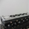
I made a little more progress last night and added some E85 safe fuel tank baffle foam in behind the stock cam cover baffle plate. It still feels really wrong shoving foam inside the engine but apparently its fine based on it pretty much being the MINES/Hi-Octane RB26 cam baffle kit and the few posts here I have found of people doing it and the lack of posts saying the foam broke down and ruined the motor... Still plan to check it frequently though lol The last step for this round of oil control modifications I plan to make is to add some -12AN fittings to the cam covers and connect them to some (already existing luckily) -12AN fittings on the sump. Basically a sudo head drain/sump breather/pressure equaliser without having to remove the motor and do the one on the rear of the head. My plan is to add them to either the tops or the sides of the cam covers at the back. unless there is a compelling reason to have them at the front on the sides which i have seen a few times though they were all on RB26 cam covers from memory so that may be due to the stock breathers being on the back and the integral baffle being different ?
-


Recommended Posts
Create an account or sign in to comment
You need to be a member in order to leave a comment
Create an account
Sign up for a new account in our community. It's easy!
Register a new accountSign in
Already have an account? Sign in here.
Sign In Now