Jump to content
SAU Community

Recommended Posts

just noticed i'm not supposed to post questions inside the FAQ/tutorial forum... so here goes :)

according to the paul's FAQ on the PFC:

"One AFM:

If you are using one airflow meter you can simply parrallel up the airflow meter signal into the second input on the RB26 ecu. The ECU will average out both signals despite it coming from the same airflow meter to work out engine load (or airflow load). "

I want to do this to my 26, and ideally run a single GM LS1 MAF or Lightning 90mm MAF. Is this confirmed to be true? It would seem that doing this would make the PFC think twice as much air is being flowed, no?

For example, if you parallel the signal, and say you are reading 2.5V on a single z32 MAF. This is then duplicated to both inputs, so wont the PFC think you are running two z32 MAFs at 2.5V and put you much further down the load map than you want to be? Seems like it to me.. or is the 26 PFC really just doing an avg'ing?

Link to comment
https://www.sau.com.au/forums/topic/167363-rb26-pfc-running-single-maf/
Share on other sites

just noticed i'm not supposed to post questions inside the FAQ/tutorial forum... so here goes :)

according to the paul's FAQ on the PFC:

"One AFM:

If you are using one airflow meter you can simply parrallel up the airflow meter signal into the second input on the RB26 ecu. The ECU will average out both signals despite it coming from the same airflow meter to work out engine load (or airflow load). "

I want to do this to my 26, and ideally run a single GM LS1 MAF or Lightning 90mm MAF. Is this confirmed to be true? It would seem that doing this would make the PFC think twice as much air is being flowed, no?

For example, if you parallel the signal, and say you are reading 2.5V on a single z32 MAF. This is then duplicated to both inputs, so wont the PFC think you are running two z32 MAFs at 2.5V and put you much further down the load map than you want to be? Seems like it to me.. or is the 26 PFC really just doing an avg'ing?

Forget the GM MAF's as they are frequency based. The lightning MAF of the SVT Mustangs will flow alot more than 350rwkw but they are a little shitty to tune down low and I say this becuase I had a little trouble with a 5.4L 310rwkw NA mustang and it would have alot more cubes to aid airflow at low speeds then any skyline.

Your best bet though would be using a little voltage divider circuit using say two 2k resistors. Just solder one end of the resistor to ground then solder the other end to the input to the PFC and the other resistor togeter then the other end of the other resistor goes to AFM signal.

Hey, I started a similar thread, and it seemed, to really get the higher resolution required, and hook up to a PFC, you'd need to use one large AFM.. as you are talking about.

>> http://www.skylinesaustralia.com/forums/in...148284&st=0 <<

One would have to bridge the connections, giving the same reading across both inputs. Then you would have to play with the AFM voltage correction tables, to get it to idle, run etc, then tune from there.

I haven't tried this yet, only theory.... but sound theory i reckon.

- M

I'm just about to play with an rb26 single maf as soon as I receive the pfc from nengun.

I had planned to simply parrallel up the airflow meter signal, and either adjust the airflow curve to suit or simply drop in the rb25 single maf airflow curve, ign and fuel maps. Doing the later it should start and drive perfectly fine. :thumbsup:

Due to the non-linear volt output of mafs; 2 mafs output being (x volts divide by 2) is not going to be the same as a single maf out put being (x voltage).

IF one didn't have access to the datalogit I'd assume one could simply tidy up the fuel map and all would be good; my only concern with that method is reduced load point usage when the afm is maxed out. I prefer to play with the airflow curve.

Its possible you could also trim the airflow voltage via the handcontrollers afm menu to get it running, then tune BUT that method is quiet coarse. Maybe not... I really won't know what is the easiest method until its on the dyno.

Fingers crossed the airflow menu % trim works well. That would make life very easy. :thumbsup:

Rob82, You lost me a little with the voltage divider. :)

Your best bet though would be using a little voltage divider circuit using say two 2k resistors. Just solder one end of the resistor to ground then solder the other end to the input to the PFC and the other resistor togeter then the other end of the other resistor goes to AFM signal.

Whats the need for this? Doesn't parralleling up the signal work? :S

i have had a few GTR come into the country with the AFM wires parralelled. It works fine.

I also did it on cats when trying to find the electrical gremlin which made it miss.

Fitting a Lightning AFM would require plotting new AFM curves, i think i have an equation somwhere to determine the load values vs voltage. I will check.

Rob82, You lost me a little with the voltage divider. :P

Whats the need for this? Doesn't parralleling up the signal work? :S

Thanks for the replies guys.

the reason rob mentioned this was b/c of my theoretical example above...

basically if the PFC is summing the two voltages and making a calculation and you simply just parallel the signal, the pfc will THINK you are flowing twice as much air when you actually only have one MAF, hence the voltage divider. However, as someone mentioned, the air flow vs. voltage is no linear, so you cannot just divide by 2.

if the PFC parallel's the signal, it still seems like it would THINK more air is coming in when it really isnt.

Regardless of the above, i would think making a rough guess at a curve should be okay, since we have complete adjustability in the 20x20 for fueling and timing. Worst case it will just have poor resolution when moving down the N Load (Y-axis) of the pfc... either being too sensitive and moving down the Y axis way too fast, or being not sensitive and sticking on the same Y coordinate, kind of like the MAF is maxed out.

EDIT: Just read the link provided by GeeTR, and it seemed to end inconclusively :) I don't think anyone has concrete proof of this working yet with airflow curves and configuration.

Edited by gawdzilla
hi,

i have researched the load axis cals in detail and it avcerages the two afms so one or two afms in parrell means the same

hmm, if the PFC does an average.. lets take the following example scenario. Running 2 z32 mafs in the standard setup...

afm1 shows 3.01 volts.

afm2 shows 2.99 volts.

average is 3 volts, and i'm flowing say X units of air

set it up in parallel and run just afm1. duplicate the voltage reading to afm2. because I was flowing X units of air before, in order to flow that same X units of air through my single afm, my afm is going to read higher voltage, no? cuz now I only have 1 afm. now we have half the cross sectional area so my single maf is going to be "working harder". then clone the signal to both afm's and we get say 3.50 volts. PFC is going to see 3.5 volts for X units of air instead of 3 volts for X units of air. Its still going to think you're flowing more air than you really are and the motor will run rich.

I could see it working if your MAF sensor was removed and placed into a tube with exactly twice the cross sectional area of a single z32 maf. Basically, instead of two 80mm MAFs you would need to run (2 x 5026 mm^2) of cross sectional area which happens to be a single ~113 mm MAF.

Is this a valid argument?

Edited by gawdzilla

I think your reasoning is spot on. However, i tend to think it will work for a couple of reasons 1) rb20 apex eng pfc is a modded 26 unit running one afm, and 2) there are correction tables for the afm to correct the difference.

oh and 3) even on the single afm equipped cars (rb20 and 25) the signals are still split into 2 before hooking up to the ecu.

Plus trent has some working examples obviously.

i agree. i'm not saying it is not possible with some minor fixes to the afm correction tables. all i am saying is that it is not a plug in and go type deal. it definitely will need a retune because your load cells at a minimum will be off, even if the rb26 just averages the signal.

when you get one afm output and run it to AFM1 and AFM2 they both read the same value and PFC uses them in its fixed load calc to work out "LOAD"

the load unit is a floating airflow load and its not in relation to the 0 to 20 scale but an arbitary number repsenting engine load.

I think your reasoning is spot on. However, i tend to think it will work for a couple of reasons 1) rb20 apex eng pfc is a modded 26 unit running one afm, and 2) there are correction tables for the afm to correct the difference.

oh and 3) even on the single afm equipped cars (rb20 and 25) the signals are still split into 2 before hooking up to the ecu.

Plus trent has some working examples obviously.

Ahh but it appears its not actually a modded rb26 one but rather a modded rb25 powerfc pro. My Ap engineering pfc had rb25 stamps internally. Crack open an rb25 power fc pro and they look identical, apart from the bodgy looking internal wiring mods. :banana:

-------

Either way the afm curve will be out because its expecting the flow of 2 x afm's not a single. As we know the afm's airflow vs voltage isn't linear so it will create slight variations.

I have no doubts; it will work. :bunny:

Time will tell how far out the airflow curve really is; Paul and I have an RB26 on their way so it should be interesting exactly how it pans out in practice. :(

the ap engineering rb20 pfc's and powerfc pro's 20 or 25 come from the same version

they are from the older first generation rb25 powerfc

they have fc commander 2.3x usually and the main board is the older style board

it has the CEX expansion slot on the board which denotes what FC version it is

i would like to know if an older vanilla 25 FC running 2.3x has anything in the CEX expansion slot

there is also another expansion slot socket but ive never seen it used

the ap eng rb20 version is the older 25 PFC but with VCT removed, 2 injectors flipped, some internal code changes and map changes

the airflow correction tables and control it setup to run whatever maf input the PFC has

so if you have a 26 PFC with twin mafs in then that table applies to the MAF load AFTER the calculatiopns have been done

the maf cals look like this;

LOAD = CORRECTION * (16384 * Airflow lookup(MAFSV) / RPM)

for twin MAFs we just avg the mafs input first then go from there

correction (from the airflow table on the hand controller) is applied after getting maf's averaged and calc'd

  • 4 years later...

I'm in the process of tuning a 26 PFC on a rb25

Having these problems

-Idle hunts like crazy using one z32 maf

- when I splice both maf ecu pins together heaps of fuel is dumped in and have to take about 75% of the fuel out to get it to idle near 14.7

- when both spliced it idles at about the 12th row of load ( idles near where it should with it the 2nd maf pins not used/ unspliced)

If I turn the maf correction down to 50% over the entire range it idles at the correct load without hunting. Will this be okay in higher rpm or will load been "non linier" mean that the loads will be wrong

I setup a RB26 PFC on a gtst (single AFM with parraled wiring). I put the AFM curve into excel from datalogit for the appropriate AFM (Z32 in this case), and 1/2'd the values.

the PFC doesn't average the 2 AFM's, it add's them together.

Edited by sav man
  • 1 month later...

Were your load values higher than normal as well as afm voltage?

I halfed the afm voltage to bring it to a single reading but the load is still about double what it should be (2300ish at idle)

I'm going to try and zero out one of the afm signals to make it read only 1 afm and use the 1 reading for it's load calc. Then %100 afm correction and rb25 z32 afm curve.

Forget the GM MAF's as they are frequency based. The lightning MAF of the SVT Mustangs will flow alot more than 350rwkw but they are a little shitty to tune down low and I say this becuase I had a little trouble with a 5.4L 310rwkw NA mustang and it would have alot more cubes to aid airflow at low speeds then any skyline.

Your best bet though would be using a little voltage divider circuit using say two 2k resistors. Just solder one end of the resistor to ground then solder the other end to the input to the PFC and the other resistor togeter then the other end of the other resistor goes to AFM signal.

Go HPX, i have a killer curve now that works wonders.

I'm in the process of tuning a 26 PFC on a rb25

Having these problems

-Idle hunts like crazy using one z32 maf

- when I splice both maf ecu pins together heaps of fuel is dumped in and have to take about 75% of the fuel out to get it to idle near 14.7

- when both spliced it idles at about the 12th row of load ( idles near where it should with it the 2nd maf pins not used/ unspliced)

If I turn the maf correction down to 50% over the entire range it idles at the correct load without hunting. Will this be okay in higher rpm or will load been "non linier" mean that the loads will be wrong

Use the votage curve table to calibrate the afm curve. I will see if i still have any of the old tunes that i can post the voltages from. I generally dont keep the old ones on the laptop anymore as its getting to crowded in the map folders.

It will only take 20mins to write a new curve with on the dyno so it not a real issue, or is it being home tuned? road tuning the curve can be painful.

Create an account or sign in to comment

You need to be a member in order to leave a comment

Create an account

Sign up for a new account in our community. It's easy!

Register a new account

Sign in

Already have an account? Sign in here.

Sign In Now


  • Similar Content

  • Latest Posts

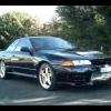
    • it takes so long to get things done but ... they are nearly there and we hitting the track soon again  So - at Perth Festival of Speed the car unfortunately had a decent off, wasnt me driving, wasnt the person drivings fault. Long story short car got sent very fast towards the wall without the control on throttle from the driver input and a disaster was averted but there was damage that needed to be fixed - carbon busted and alot of bent bits The splitter got munched and had to go back to get fixed - took a bit to get it there, fixed and back but got a surprise package when a new double element higher DF splitter came back - nice surprise !  and first person to have one     At a car show I took the car too some punks stole one of my carbon indicator blanks and stomped on the other so had to get a new set of headlight / indicator combo from tops stage so got front fender vents as well to put in the order     While all this was happening the new MCA golds turned up and did some fiddling around with those   Put in the flappy paddle system and clutch lockout wiring/ system   We have also put shorter gearing in top top it out at 300 kmph in 6th gear  where previously I held 5th to 282 at SMP and 277 in Perth   Looking for better control and faster acceleration     I wasnt intending on doing pedal box I was managing with the brake master replacement system I had going on and adjusted std pedals but on applying the clutch switch to the old system we found the *insert technical word here * bar that goes from the pedal to the master was bent about 40 deg and about to snap = lucky find otherwise be a bad bad time - discussion was had about getting a custom bar built to withstand the load but in reality it was time      making any suspension, wheel or anything adjustments to date has been a nightmare - aero off, adjust, check and repeat - time consuming and hard - short of going full airjack system we fashioned some external manual car lifts this will make life a million times easier     All the bent framing, some intercooler pipes and other has been fixed and replaced and after 6 months I finally have the car back at home in my control so its get to work on it, set ride heights, wheel align and will start track testing again soon   So ultimately other than a few flashy bits nothing actually looks likes its been done but in reality alot has. Typical   We'll see how all this goes        
    • I'm far from an expert, but for sticking bits of metal together occasionally I got a MIG, the biggest one I could get with a 10a plug (because while I have some 15a GPOs around, they are not everywhere).  Also, because I get through SFA, I just buy the small disposable gas bottles at Bunnings, I'm not opening a BOC account to get through 1/10th of a full size bottle each year
    • FWD is different though.
    • Ignore the BOV / recirc valve question. You have an NA and shouldn't have one. If there magically is one though... It should be removed, though it shouldn't really effect it in the way one will for a turbo motor with it venting to atmosphere while running an afm.
×
×
  • Create New...