

Announcements
-
Similar Content
-
-
Latest Posts
-
 Had another look at the car and I noticed the fuel pump isn't priming on ignition. I'd taken out the pump from the boot to siphon out the old fuel, so maybe I've knocked something loose or broken a wire putting things back together. Will go back with a multimeter and try to work out what's stuffed. Kinda hoping it's the pump itself thats gone so I can upgrade it
 -
 Yeah agreed, you can't assume that shop are they only people who ever had to work on it. It was just a guess on the mods based on how things were done back then. You can check the Air Flow Meters by the part number on their tags, they are likely either Z32 or Nismo ones (both read about the same but the Z32 one is a little larger while nismo is stock size but supports the higher airflow like a Z32). And yes, all that would get you to 450hp / 340kw To tell what is happening with the turbos, you want a photo of the tag on the core, that will say what it was made out of (they can retain the front and rear covers to make the plumbing easier)
 -
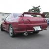
 I'm selling my personal race car. 1992 BNR32 Skyline GT-R About eight years ago the engine developed the dreaded low oil pressure problem. I removed it and found the issue. However shortly after I moved half way across the country, moved my work shop, bought a house, got married, then moved my shop again to it's permanent location for the time being. in turn I do not have the time to race this car as it should be. In turn the engine I built for this car will end up in my street car and this car I hope finds a home with someone who can use it to it's full potential. The roll bar was built by Jason Noren Fabricaiton in Pomona California to SCCA and NASA Specs. The car used to compete in redline time attack and global time attack enthusiast class. It also has a fire suppression system. The car is with me at my workshop in Kyle Texas, USA. Shipping it is no problem, I can personally deliver the car to the port of either Houston or Los Angeles. Any other port depending on where it is may require transport but we can always work that out. The chassis itself is rust free, rear quarters and under fenders are free of any rust so it's a very solid foundation for anyone who wishes to move forward with it. As posted and at the asking price of $20,000 USD the car includes all of the following; All OEM Body panels, front fenders, rear bumpers etc. OEM Nissan Projector headlamps (Pictured N1 lamps were removed) OEM Nismo Side Skirts / Extensions OEM Rear Spats Front & Rear Subframes are installed car is full roller Rear Subframe has Cusco Camber Arms, Whiteline HICAS Elimination Front Subframe has Whiteline tension rods and whiteline Sway bars w/ endlinks. Buddy Club N1 Coilovers All chassis wiring and engine wiring is in tact. Attessa System is fully in tact and was functional before engine removal. BCNR33 GT-R Brembo Brakes F+R with Endless MX72 Plus Pads, DBA Rotors & Stainless Steel Brake lines Billion Racing Radiator Billion Radiator Hoses Fluidyne Engine Oil Cooler Accusump System (trunk Mounted) 5 Speed Transmission w/ Transfer Case F+R Prop-shafts Rear Differential With rear Axles. Nismo Gauge Cluster Nismo Clutch + Flywheel Essentially what is needed to make this car running and driving again is as follows: A working Engine, an ECU, and time to put it together. The price posted is or best offer as I am willing to remove some components to accommodate price to a certain extent. If any serious buyer wants full detailed pictures, videos, or any questions I'll be happy to answer them. I believe this car is priced to move quickly considering it's a rust free and very straight chassis but always open to fair negotiation. I can be contacted via phone or email. (+19517081648) email is juan@bardabe.com
 -
 So...to my (and my mechanics doing the swap) surprise...the oil pan from NEO engine does not fit 100% and needs to by modified like this: It is not a huge problem but in the future i want a "proper" oil pan. So question is...what different oil pan can i get to fit without any problems and modification? Thanks!
 -
 Some more info I found. These are the last entries Yoshikiyo Fujii made on his blog before he passed away in 2009: http://blog.livedoor.jp/fujii_dynamics/ And finally this is where the workshop was situated: https://maps.app.goo.gl/HhTPtHzt3WVcBTiEA
-


Recommended Posts
Create an account or sign in to comment
You need to be a member in order to leave a comment
Create an account
Sign up for a new account in our community. It's easy!
Register a new accountSign in
Already have an account? Sign in here.
Sign In Now