Jump to content
SAU Community

Recommended Posts

I was under the impression that the stock cooler piping was 2.5 inch ID (63mm).

I got a piping kit for an fmic, and measured the piping to be 2.25 inch ID (~57mm)

I thought this might be the wrong kit, so i measured my stock 33 smic inlets, and the leftover pipes from the R34smic upgrade. They measure 2.25 inch ID.

So, what size cooler piping is normal for the fmic kit for R33? Has anyone bothered to measure? Or just assume, as I did, that its 2.5 inch?

the hot side is often smaller than std but the cooler side is larger. i know on the big sr20 kits (like on our car previous) the hot side is usually around 57mm and the cool side is 70 or 80mm depending on kit.

its the just jap type 2 kit. it's supposed to be tube and fin, but i have a feeling they gave me the wrong cooler. looks like bar and plate to me. and also measures 600x280. i'm currently waiting for a reply about that. here are pics of the cooler they gave me

the piping comes in a seperate box, and it looks to be the correct shape for R33. but the diameter threw me off. after measuring my stock pipes, i'm not sure what size its supposed to be now. has anyone actually measured theirs?

yeah the piping kit looks correct for r33. i havent tried fitting anything yet, but it's basically the same shape as the others ive seen.

i just spoke to just jap, and they told me the piping kit is 2.25 on the type 2 (greddy copy) in keeping with the stock piping size.

they also said the new type 2 coolers are all bar and plate. they found a tube and fin in stock for me to pick up.

ive always assumed tube and fin flow better, less restriction, but cool less than bar and plate. is this right? coz now i'm getting conflicting info.

Yeah thats the general consensus between the 2.

I opted for the bar and plate. I'm using the stock turbo, as if flow is going to be hugely affected on the low flow a stocker pushes. Plus I'd rather have the better cooling side of things. Up to you really.

ive always assumed tube and fin flow better, less restriction, but cool less than bar and plate. is this right? coz now i'm getting conflicting info.

Other way round. bar and plate is cheap to make and hence is used more here in these types of kits.... all the better cores are a tube and fin type design.

so tube and fin would be a better choice? coz thats what i was going with

nissan smic's and gtr coolers are tube and fin. as well as the hks etc.

Edited by Munkyb0y

:) yes i see

well i measured my stock cooler piping. the one that joins to the standard crossover pipe. it seems to be 2.25 inch.

so i guess the same size (2.25") fmic piping on a stock turbo setup is probably the way to go.

updated the link with pics of the tube and fin cooler from just jap.

http://tony.ikkon.com.au/fmic/ - (scroll down for tube and fin)

looks ok to me. what do you think?

Edited by Munkyb0y
  • 1 month later...

fitted the cooler. drives nice. no added lag. still as responsive. feels like it pulls a bit harder.

i'm thinking it'll benefit from another tune. what do you guys think?

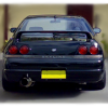
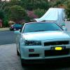
here's how it turned out.

post-29392-1197430267_thumb.jpg post-29392-1197430284_thumb.jpg

thanks man :(

the reo bar was easy. i just cut 2 small wedges out of each side of the bottom section. after i sprayed it black, you wouldnt even notice it's been cut.

the front bar needed a bit more attention around the cooler piping, but all in all, it was just a matter of patience.

Edited by Munkyb0y

lol. depends on the bar too i guess. does yours have a huge opening for the cooler? also, i hung my cooler from a single bracket in the centre, off my radiator support. the ones with the 2 mounting points that bolt up to the reo, sit alot more forward, so would require alot more cutting of the reo bar.

i managed to squeeze a cold air intake pipe just above the cooler piping in the passenger side opening (it's the blue rectangle-ish thing). i wish there was more room, but thats all i've got to work with there.

better than nothing i guess.

post-29392-1197602578_thumb.jpg

Edited by Munkyb0y

Create an account or sign in to comment

You need to be a member in order to leave a comment

Create an account

Sign up for a new account in our community. It's easy!

Register a new account

Sign in

Already have an account? Sign in here.

Sign In Now


  • Similar Content

  • Latest Posts

    • I'm interested if anyone agrees with what you've said, and can give a good reason. Temperature of powder coating should be below any temperature you'd use to alter the wheel structure.  Powder coat typically 200 to 250. Annealing if that's what people are claiming would be occuring, starts at 300, and depending on the alloy, can need even up at 400+.   That's the only part I can think of that could cause an issue that people are believing it's from the rim losing hardness and becoming too soft.
    • Negative probe should be on the cars chassis. Positive on the wire.   Start as said above by unplugging everything (unplug the lights, and switches. Now at the switch, there is a wire from the fuse, to the switch, so out your positive on that terminal. It should read open circuit. If it reads something, especially a stupid low value, the short is somewhere between the fuse and the switch. If that's fine, now put the positive probe on the wire that goes to the headlight (at the switch plug). If it reads stupid low, the fault is from the switch, to the headlight.   Another quick test, is take the whole LED light setup from the left, and plug it into the right side, does it still blow the fuse? If you put the right hand side led light setup on the left hand side wiring, does the left hand side wiring now blow?  If the blowing fuse swaps from right to left doing this, your LED lights are the issue.
    • Anyone know if it's a problem to powder coat forged alloy wheel centers (Rays/Volk GT-C). some say it's bad and can damage the alloy, some say it's not a problem.
    • Hey guys, I'm reviving an old post but I'm finally getting around to working on this now. I removed the battery to get a better look at the wires and i traced the wires from the headlight to the fuse box in the engine bay, but the wiring looks fine? The wiring for the R/H headlight is 3 wires and then is bundled up with the large diameter wire that goes underneath the fuse box. I didn't take it apart yet. I know you said that its a short circuit somewhere between the fuse box and the headlight. But could it be the headlight switch on the dash? Also, i pulled out my multi-meter and set it on the Ohms, but i'm not sure where to put the negative probe and the positive probe.     
    • I have a 2 lt in Sydney. It was fitted on a R33 GTR, not used for several years . If you are interested email me on: [email protected] I'm not on this forum much .
×
×
  • Create New...