

Announcements
-
Similar Content
-
-
Latest Posts
-
 Stock ECU (or more accurately stock tune) absolutely refuses to go over 10psi and behaves like you have seen. The Nistune is the same if it is the stock tune. If the Nistune chip has been tuned, the resulting tune could be literally anything for any combination of parts. The Nistune just makes the stock ECU Tunable.
 -
 So stock ECU does not like anything above 10 psi? That Nistune one is just for "try" if it will be any different, I know it need to be tune for that. I know but YOU may know about these problem but i/we dont. They few little Skylines here let alone people who know anything about tham so that is why iam asking here
 -
 So now we have a radiator with no attachments whatsoever. It lifts up with a particularly tight spot between the drivers side air box mount and the lower radiator outlet, but if you've got this far you will sort that too. This is the lower mounts with the rad out so you can see where the rubber bushes go, it is a straight shot upwards Done! Assembly is the reverse of disassembly, with blood less likely to be shed.
 -
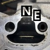
Right, onto the second last trick. The Air Con condenser is mounted to the front of the radiator and stays in the car when the radiator is removed. There are 2x 10mm headed self tappers holding the top of the condenser to the radiator, remove those The bottom of the condenser is attached to the radiator with clips. You need to lift the condenser out of those clips and clear (up, then forward). f**ked if could work out how to do that last bit with the front bumper on. I hope you can, and you share the trick. Bumper removal probably deserves its own thread one day once I've recovered the will to live, but basically you need to remove the wheels, front inner guard liners (clips and 10mm headed bolts), the self tapper between the guard and the bumper at the rearmost point of the bumper (same as an R32 that bit), any remaining clips at the top/front of the grill, an absolute bastard design with a plate that holds the top of the bumper above the headlight each side (only 1 bolt which is tricky to get to, but the plate catches 2 places on the bumper and must be removed....carefully!) and push clips between the bumper and guard under the headlight. If you've done all that you will be faced with wiring for the fog lights on both sides and in ADM Q50 RS at least, 4 nasty tight plugs on the driver's side for the ADAS stuff. So, the clips at the bottom look like this on drivers side (looking from the front) And on the passenger side (also from the front), you can see this one is already out Clearance on both of these are super tight; the condenser needs to move up but the upper rad support mount prevents that, and the radiator can't move down far because it is (rubber) mounted. Once you achieve the impossible and drop the condenser off those mounts so it does not stop the rad moving, you are good to go
-
OK, next the shroud needs to come off and there are a couple of tricks. Firstly, there is a loom from near the passenger side headlight to the fans, coolant temp sensor etc and there is no plug to undo. In my case I was OK to leave the shroud on top of the engine so I just undid the passenger side fan plug and about 10 of the clips which gave enough free wire to put it aside. The fan plugs were super tight, the trick I used was a small falt screwdriver to push down on the release tab, then a larger flat screwdriver to lever the plug out of the fan unit....be careful with how much force you apply! If you need to remove the shroud altogether for some reason you will have to deal with all the plugs (tight) and clips (brittle)....good luck. I removed all of the clips and replaced them with cable ties that I will just cut next time. Also, in the Red Sport / 400R at least, the intake heat exchanger reservoir hose is bolted to the shroud in 2 places with 10mm headed bolts; so remove them (the hose stays in the car; no need to undo it at the t fittings down at the radiator lower mount. Once you've dealt with the HX hose and the wiring loom, there are 3x 10mm headed self tappers holding the top of the shroud to the radiator; remove those. The shroud then lifts out of the bottom mounts where it sits on the radiator, up and onto the engine out of the way. Simples
-


Recommended Posts
Create an account or sign in to comment
You need to be a member in order to leave a comment
Create an account
Sign up for a new account in our community. It's easy!
Register a new accountSign in
Already have an account? Sign in here.
Sign In Now