
Announcements
-
Similar Content
-
-
Latest Posts
-
 That is correct, I have a forged RB25/30det NEO hiding away safely and I wanted to use the very rare greddy vct adj cam gear on this new setup and so I just used the whole thing on my s1 instead of pulling it appear because I'm lazy af 😅🤌🏼
 -

By Dose Pipe Sutututu · Posted
But but but.... You have a NEO Cam sprocket Sure am ☺️ -

-
Thanks brother, are you NHB ? RB25 s1 my man hahahah 💀
-
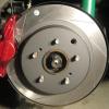
 New tyres bleed the brakes sort out lights and historic registration time for the sub r31 IMG_0551.mov
-


Recommended Posts
Create an account or sign in to comment
You need to be a member in order to leave a comment
Create an account
Sign up for a new account in our community. It's easy!
Register a new accountSign in
Already have an account? Sign in here.
Sign In Now