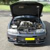
Jump to content
SAU Community

Recommended Posts

guys i have posted this pic and put arrows to the location,all i need to know if this is the place to run the line for a mechanical speco boost gauge?

ive put the pic up as when i have asked before without a pic the only answer i got was that the guy used a t-piece on his which pretty much didn't help me at all as i needed to know where to run it from.

please let me know.

post-40900-1253600957_thumb.jpg

Link to comment
https://www.sau.com.au/forums/topic/289045-please-take-a-look-at-the-pic/
Share on other sites

I have been told a number of times ... (and I have done it this way and I also have a speco mechanical boost guage) to t-piece it off the hose that connects at the front of the stock bov...

  • 3 weeks later...

sorry for bringing up an old topic but rather do this than make a new one,i decided to use the hose that goes to the stock bov as its best to fit the t-piece but i have another problem.

with the speco mech 2" boost gauge are they meant to come with 2 compression sleeves?cause mine only has one and also when i use the only compression sleeve and one of the compression nuts and do it up tight onto the boost gauge the white pressure hose can be pulled out very easily is this normal?

there should of been a round brass ring that only just slips over the white hose this ring needs to be tight when slipped on to help with the crimping when nut is tightened. mine had the right size ring for the white hose that came with it.

Create an account or sign in to comment

You need to be a member in order to leave a comment

Create an account

Sign up for a new account in our community. It's easy!

Register a new account

Sign in

Already have an account? Sign in here.

Sign In Now


  • Similar Content

  • Latest Posts

    • My understanding is that UV tends to accelerate the aging process. If the car has been garaged, then you could probably get away with extending beyond 10 years. FWIW, in 2015, I had tyres on my 180B SSS that had a 3-digit code (2 for week, 1 for decade), ending in 0, so could have been more than 30 years old, but still worked fine. I did replaced them very quickly, though, once I discovered what the code meant!
    • But we haven't even gotten to the point of talking about stateless controllers or any of the good stuff yet!
    • You guys need to take this discussion to another thread if you want to continue it, most of the last 2 pages has nothing to do with OP's questions and situation
    • And this, is just ONE major issue for closed loop control, particularly using PID. One such issue that is created right here, is integrator wind up. But you know GTSBoy, "it's just a simple PID controller"...  
    • Nah. For something like boost control I wouldn't start my design with PID. I'd go with something that originates in the fuzzy logic world and use an emergency function or similar concept. PID can and does work, but at its fundamental level it is not suited to quick action. I'd be reasonably sure that the Profecs et al all transitioned to a fuzzy algorithm back in the 90s. Keep in mind also that where and when I have previously talked about using a Profec, I'm usually talking about only doing an open loop system anyway. All this talk of PID and other algorithms only comes into play when you're talking closed loop boost control, and in the context of what the OP needs and wants, we're probably actually in the realm of open loop anyway. Closed loop boost control has always bothered me, because if you sense the process value (ie the boost measurement that you want to control) in the plenum (after the throttle), then boost control to achieve a target is only desirable at WOT. When you are not WOT, you do not want the the boost to be as high as it can be (ie 100% of target). That's why you do not have the throttle at WO. You're attempting to not go as fast as you can. If the process variable is measured upstream of the throttle (ie in an RB26 plenum, or the cold side pipework in others) then yeah, sure, run the boost controller closed loop to hit a target boost there, and then the throttle does what it is supposed to do. Just for utter clarity.... an old Profec B Spec II (or whatever it is called, and I've got one, and I never look at it, so I can't remember!) and similar might have a MAP sensor, and it might show you the actual boost in the plenum (when the MAP sensor is connected to the plenum) but it does not use that value to decide what it is doing to control the boost, except to control the gating effect (where it stops holding the gate closed on the boost ramp). It's not closed loop at all. Once the gate is released, it's just the solenoid flailing away at whatever duty cycle was configured when it was set up. I'm sure that there are many people who do not understand the above points and wonder wtf is going on.  
×
×
  • Create New...