
Rb26 Rocker Cover Mounted Catch Can Install

Announcements
-
Similar Content
-
-
Latest Posts
-
 A little follow up here on the ceramic coating. We've had storms galore here and I've done a few ks, enough to gross them up Consensus is that they didn't get as dirty as usual, the coating definitely repelled a little of the dirt and I think they kinda snowball. They get a little dirty and then they get dirty faster which makes sense. Cleaning them regularly would allow them to protect better. Cleaning was a breeze. I tried first to just hose them off which, unsurprisingly, did nothing. But, making the wheels wet and then just wiping them over with a used but clean microfibre cloth was all that was required. I didn't need any cleaner at all, just water and a cloth. The wheels look amazing again.
 -
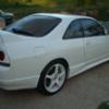
Gave her a nice wash today and took extra time to clean off the tree sap and tar and crap. We have a usable garage now so she'll stay cleaner longer. Took a few snaps in some nice light afterwards.
-
 OK, solid mount Z1 diff brace is in, pretty straightforward, it picks up 3 diff hat bolts and ties them to 2 support bolts on the subframe. Pretty sure someone else on here said they had reduced axle tramp with this but mine was already pretty good for smooth wheelspin, and still is....will see you this goes over time and whether I end up with a broken rear diff hat
 -
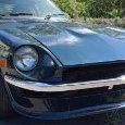
 Ah yes, but the part in my hand was actually painted and fitted by me! I knew any front lip was likely to be sacrificial but I've had to fix it twice already... by the time I buy a fibreglass fixing kit, sort out sandpaper blocks, buy some fibreglass filler, body bog, spend the time and effort for a 'Greg' result... a new one being $290 seems like it's the better way to go and spray that with bedliner/raptor coat and we're all pretty again.. Would have preferred it last more than a month though. Them's the breaks I suppose.
 -
 I find it funny that the USA is finding out all this really really weird stuff, and people from the USA are coming here treating it like gospel, yet, all the info on solving those issues is here on these forums for the last 15 odd years... Also, I know how much heat it takes to ignite the hood lining of an R33 skyline. I worked it out myself... It also took a LOT of time, and heat for it to do it... Big single, and I needed to drive the car, so retarded the timing off to "protect it". Yeah, that was a bad move for cruising on a freeway with only 15 degrees of timing on it. That was a lesson I learned around 2009. So that's over 15 odd years ago. Aligning water and oil, that's identical for any turbo engine, it's not Japanese specific. If a shop doesn't know how to make sure the core is rotated the right way, then they shouldn't be touching any turbo engine. That's not a matter of "We haven't had Skylines for that long here"...
-


Recommended Posts
Create an account or sign in to comment
You need to be a member in order to leave a comment
Create an account
Sign up for a new account in our community. It's easy!
Register a new accountSign in
Already have an account? Sign in here.
Sign In Now