Jump to content
SAU Community

Recommended Posts

  • Replies 378
  • Created
  • Last Reply

Top Posters In This Topic

Top Posters In This Topic

Posted Images

By larger crank do you mean reginding it further for a slight increase in stroke?

Yes its a larger crank but not the one from this first engine re-ground again. Ive made 5 cranks so far while experimenting with the crank re-grinding machine and different rod and piston combinations. The latest crank is a hair under 88mm which is the largest an RB30 crank can be offset ground too with SR20 rod journels. I had a go making a crank with honda sized rod journels too, but when I saw how small the honda rod journels are next to the rb30 mains journels after the machining... well I had second thoughts about using it in the first engine.

With the 88mm stroke, the conrod shaft gets very close to the bottom of the sleeves/cylinders at 90 and 270 degrees. Because the cylinders are sleeved, the cylinder cant be shaved to provide more rod clearance without compromising the sleeve strength and and seal to the block. Its only possible to fit this stroke because of the shape of the pauter rods. If I were using H-beams like carillos or eagles the stroke wouldnt clear the block. Max capacity would be 3220cc if I had used Dartron's "Super Ductile Iron" sleeves as they allow bores up to 88mm. 87.5 is the max for the block I am using, so 3180cc.

If someone had purchased a Tomei/HKS 77.7mm crank (or similar) you could replicate a "high deck" :(

Yes that would be pretty easy but I won't be having a go at that till Im done playing with RB30 and RD28 cranks. The inital idea was to make a cheaper stroker engine, and a hi-deck is more of a high horsepower class engine. While this project isnt cheap anymore but it certainly is fun.

I just ran the numbers on your high deck too. SR20 rods on a 77.7mm crank makes a 1.75:1 rod ratio with a 16.6mm spacer and 30mm comp height pistons. That would be how i'd do it. The spacer needs to be thick so it can support a 1/8th BSP external oil feed.

Have you tried I- beam rods? not sure if they will give you any more room to play with over the Pauter ones, but maybe worth having a look at.

For the Lulz i test fitted an RB30 crank in a 25 block last night, nearly fits, would just need to tweak a few spots and move the oil squiters.

Have you tried I- beam rods? not sure if they will give you any more room to play with over the Pauter ones, but maybe worth having a look at.

For the Lulz i test fitted an RB30 crank in a 25 block last night, nearly fits, would just need to tweak a few spots and move the oil squiters.

Did the counterweights on the RB30 crank clear the block near the edges of the cylinders? They dont with an RB26 block, which might mean the 26 block has more material around and under the base of the cylinders to add more block rigidity.

Getting around the squirters is easy, have a look at the pics of my crank and the photo with the squirter and how it fits the slots in the counterweights.

Conventional I-beams are still square in the shaft of the rod. The pauter rods are at their narrowest where it matters (above the rod bolts).

6-07_rods_003.jpg

I think that 88mm is plenty large enough. At that stroke size it is hard to get a long enough rod in there to keep the rod ratio sane as well. 5.4 or 5.5" chevy length rods are the next way to go.

Nah they didnt quite clear, would just need a touch of machining done to get the counter weights to clear.

Its not really somthing I would consider being that I have a 30 block already and a RWD skyline, just had both blocks and cranks side by side in the garage.

I see what you mean with the Pauter Rods, they look very nice.

I may pull the oil squirters out over the weekend and see how the crank goes though, you have me curious now lol.

Here's the other option to get the crank to clear the squirters and base of the cylinders. This is the first crank I made that is knife edged and modified to use honda RSX rods. This one is an 87mm stroke too.

post-26553-1275025274_thumb.jpg

I was tossing up ideas today at work (been a quiet day) about using a 25 or 26 crank in a 30 block with 6.25" rods, would make an excelent base for a megga RPM RB imo.

Sorry dont mean to go off topic too much.

P.s I Like that crank

I was tossing up ideas today at work (been a quiet day) about using a 25 or 26 crank in a 30 block with 6.25" rods, would make an excelent base for a megga RPM RB imo.

Sorry dont mean to go off topic too much.

Interesting idea, though you would want to use aluminium or titanium rods if you went down that path.

There is a point where the increased rod ratio (which lowers piston speeds and acceleration rates allowing a safer high rpm) is offset by the increased mass of the extra long rods. That increased mass combined with the intended higher RPM operation will up the load forces applied to the rod bearings considerably. If you were able to score some alloy chevy 6.25" rods cheap 2nd hand it might be worth a try.

I can calculate out the piston acceleration rates for this setup if you want, and that combined with the mass of the rods will give you your bearing load forces.

Dont worry your self too much about my idea's I doubt Id ever do anything with them, Im just very interested in what can be done with RBs due to the fact that not many people do things differently with them.

Well I couldnt help myself and did the calculations anyway. Its interesting looking at the numbers and how force increases with RPM and mass.

Calculations assume the following data:

RB26 rod weight - 473 grams

SBC Chevy 6.25" rod weight - 643 grams

RB26 Piston weight - 320 grams

Standard RB26 Calculations

Stroke - 73.7 mm

Rod - 121.5 mm

Ratio - 1.65 mm

Acceleration @ 8000 rpm - 33.2 m/s^2

Acceleration @ 9000 rpm - 42.0 m/s^2

Acceleration @ 10K rpm - 51.8 m/s^2

Total Rod + Piston mass - 793 grams

Rod loading @ 8000 rpm - 2346 gram force (26.33 newtons)

Rod loading @ 9000 rpm - 3396 gram force (33.31 newtons)

Rod loading @ 10K rpm - 4188 gram force (41.07 newtons)

RB26 crank with 6.25" rod Calculations

Stroke - 73.7 mm

Rod - 158.75 mm

Ratio - 2.15 mm

Acceleration @ 8000 rpm - 31.4 m/s^2

Acceleration @ 9000 rpm - 39.7 m/s^2

Acceleration @ 10K rpm - 49.0 m/s^2

Total Rod + Piston mass - 963 grams

Rod loading @ 8000 rpm - 3083 gram force (30.23 newtons)

Rod loading @ 9000 rpm - 3898 gram force (38.23 newtons)

Rod loading @ 10K rpm - 4811 gram force (47.19 newtons)

man you are seriously smart with this stuff. ive done a bit of stroker, rod/stroke ratio work myself with v6 commo engines.

i had the idea of a stroker using honda rods myself about 6months ago, but i dismissed it cos of the small ass journal size and the poor rod/stroke ratio. ive heard rumors that some form of american race cars use honda size rod journals in v8s so im guessing the strength is achieveable. but theres alot of difference between and atmo v8 and a turbo straight 6.

how do u think it would go in a conservative HP build?? say an engine looking for strong low down torque and response, but only good streetable power say 300kw max.

EDIT: also i forgot to ask why go a MLS head gasket?? from what i hear from the commo guys they do nothing but leak. wouldnt a copper head gasket been more than capable of doing the job??

Edited by Raysboostin

As Mike guessed I have quite an array of spreadsheets for calculating out all the geometry, etc. What started out as a couple of basic spreadsheets now calculate every aspect of the open deck engine. It was necessary so I could see what would work on paper before going out and needlessly wasting money.

Yes ive heard of V8's using honda journel'd cranks as well, and they rev the hell out of them too. The reason they get away with this is that there is still sufficent main to big end journel overlap on the crankshaft to provide the crank with the necessary strength to survive. See Pic:

0710phr_03_z%20crankshaft_tech%20.jpg

The V8's in question are still running 5lt + in capacity but are able to do so by using 4" and larger cylinder bores. The stroke on the crank is usually either standard or even reduced. The smaller bearing diameter of the honda journel provides less rotational friction/drag between the rod bearing and the crankshaft. Honda have well proven their bearings to survive 10K+ RPM in race applicaitons. But in a V8 with a longer rod and a much heavier piston they have to use alloy rods to keep the stress loads on the bearings down.

The other way around this issue is to custom grind a crank from billet material and use much larger main bearings. This has been done for years in the vw after market industry allowing up to 3lt 4 cylinders to be made using 90mm stroke cranks and 4" bores, and usually use a 50mm chevy size rod bearing. This might sound a little excessive, but it is actually being done more often than you might think. The Australian 4 cylinder all motor record holder made his own crank from scratch. He used massive ford clevland mains and chevy big ends to get a strong as hell 2.8lt 4 cylinder crank. I'd love to have 1/2 of his engineering skills.

I think for 300kw, yes you would get away with honda journels, but in the end there isnt much benefit of going that way. The 300kw gtr recipe is very well known (GTSS's). Also, the honda version of the crank I made first was just an experiment. And while the SR20 rod version of the current/next version of the build will also work, I have since refined the design further and have a much better rod journel setup on 2 other cranks that works out to be cheaper and stronger.

All this asside, the main priority is getting a spacer plate sealing system to work. And yes, copper or even a plain gasket would have worked far better than the MLS gasket. The reason I chose to use an MLS in the first engine was I took the advice of someone who had built similar engines, yet they hadnt seen my spacer plate design. It doesnt matter though becuase its all part of the learning experience. I didnt expect to get it 100% right on my first attempt. I doubt OS Giken managed to get it right on their first attempt as well. I am however expecting great things from the next build.

  • 3 weeks later...
Update?

Good timing to ask that question as I picked up the last of the machined parts today, and tomorrow afternoon I'll be filing 24 piston rings and cleaning everything so re-assembly can start this weekend. All going well the new and larger RB315 will be back together again and running in a weeks time.

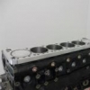
I made some progress today with the re-assembly of what is now an RB315. The rotating bottom end is now ready for a head and sump. I will hopefully be putting on the head and sump tomorrow, and with any luck starting the engine friday or saturday. A few pics of this build.

The main differences between this build and the first prototype is that I am now using a standard head gasket, which has 3 benefits. 1, cheap, 2 seals better on a surface that will change with temperature differences, 3, handles big horsepower when o-ringed.

These pistons are also different to the wisecos I used in the first engine. Im using CP's this time, and they are also thick crown flat tops so are suitable for the 22-24lb boost that will be required to make the engine deliver the 450kw goal I am after.

post-26553-1277032307_thumb.jpg

post-26553-1277032333_thumb.jpg

post-26553-1277032358_thumb.jpg

post-26553-1277032381_thumb.jpg

post-26553-1277032406_thumb.jpg

post-26553-1277032425_thumb.jpg

post-26553-1277032443_thumb.jpg

Create an account or sign in to comment

You need to be a member in order to leave a comment

Create an account

Sign up for a new account in our community. It's easy!

Register a new account

Sign in

Already have an account? Sign in here.

Sign In Now


  • Similar Content

  • Latest Posts

    • The GTT probably only has the same little bag of tools that the R32 had, which contained useless pliers, a spanner or two, a screwdriver thingo, and the handle and crank stuff for the jack.
    • ? 2s of searching finds this thread  
    • Could someone post some pictures of the factory Jack , tools, spare tire and how they were in a 1998 ER34 2 door skyline originally?
    • UPDATE: Hi all!  As we are getting towards the end of this thread where I’ll showcase final dyno numbers and graph, I wanted to provide an update. Tao from HyperGear has done an amazing job building the custom divided T3 housing for the G30. Communication was flawless, price was great, and now the housing is estimated to arrive in 7-10 days! Very very pleased. I must add, if someone is looking for an affordable turbo and end up reading this thread, I would recommend HyperGear. Genuine brands are the way to go as their proven reliability, predictable performance, and there’s a plethora of information available for specs, flow, and more. This HyperGear recommendation is based on their excellent communication, dedication, and willingness to listen to their customers. I particularly liked their ability to create custom adaptations tailored to specific needs, which is a HUGE benefit over other brands. And if we consider the HyperGear provided dyno results, it adds reassurance knowing their turbos can compete against genuine brands. Next update will be after the dyno!  
×
×
  • Create New...