
Spacing Down The Subframe To Fit An Rb30dett In An R32 Gtr

Announcements
-
Similar Content
-
-
Latest Posts
-
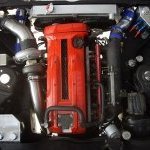 Just planning to have the wiring neat and hide as much as possible.
 -
 The sodium acetate, mixed with citric acid, doesn't actually buffer each other. Interestingly though, if you used Sodium Acetate, and acetic acid, THAT becomes a buffer solution. Additionally, a weak acid that can attack a metal, is still a weak acid that can attack a metal. If you don't neutralise it, and wash it off, it's going to be able to keep attacking. It works the same way when battery acid dries, get that stuff somewhere, and then it gets wet, and off it goes again breaking things down. There's a reason why people prefer a weak acid, and it's because they want TIME to be able to be on their side. IE, DIY guys are happy to leave some mild steel in vinegar for 24 hours to get mill scale off. However, if you want to do it chemically in industry, you grab the muriatic acid. If you want to do it quicker at home, go for the acetic acid if you don't want muriatic around. At the end of the day, look at the above thumbnail, as it proves what I said in the earlier post, you can clean that fuel tank up all you want with the solution, but the rust that has now been removed was once the metal of the fuel tank. So how thin in spots is your fuel tank getting? If the magazine on the left, is the actual same magazine as on the right, you'll notice it even introduces more holes... Well, rust removal in general actually does that. The fuel tank isn't very thick. So, I'll state again, look to replace the tank, replace the fuel hanger, and pump, work out how the rust and shit is making it past the fuel filter, and getting into the injectors. That is the real problem. If the fuel filter were doing its job, the injectors wouldn't be blocked.
 -

By GabsReDeal · Posted
Despite having minimal clothing because of the hot weather right now, I did have rubber gloves and safety glasses on just in-case for most of the time. Yes, I was scrubbing with my gloves on before, but brushing with a brush removes the remaining rust. To neutralize, I was thinking distilled water and baking soda, or do you think that would be overkill? -

By joshuaho96 · Posted
You can probably scrub the rust with a toothbrush or something. After you get the rust off flush well with water to neutralize and you will probably want to also use a fuel tank sealer to keep it from rusting again. -
By joshuaho96 · Posted
The sodium citrate solution is designed to buffer the citric acid to keep it from attacking metal quite so much, the guy that came up with that recipe did a ton of testing on how much metal loss occurs over time and it's nothing crazy unless you forget about it for months:
-


Recommended Posts
Create an account or sign in to comment
You need to be a member in order to leave a comment
Create an account
Sign up for a new account in our community. It's easy!
Register a new accountSign in
Already have an account? Sign in here.
Sign In Now