
Announcements
-
Similar Content
-
-
Latest Posts
-
 I'm thinking that this is such a small part of the problem that you could easily forego the vac pump and just achieve 90% of what you need, which is keeping the gate open when off boost. It's not as if there are not already techniques to keep a gate fully closed under boost. After all, you have boost. Just use a wastegate actuator that will allow you to apply the boost on the appropriate side, just like every external gate out there.
 -
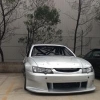
 Heres another fitment photo. redrilled the pattern to 5x112, and threw my audi´s rims on. had to touch the upper control arms with grinder, because the "sharp corner" was sticking about 2-3mm on the tire path. i have the "fender lip" mostly cut off, otherwise these (too) would contact with it. 20x9.5 ET25 rear 265/30 20x8.5 ET20 front 255/30 they are temporary, and look too big for the chassis. searching for 19s to it.
 -

-
From experience, it will come back to bite you haha.
-
Background: my BMW 225i hatchback (rebodied MINI/X1) came with 3x RE003 and 1x Goodyear Asymmetric something. The RE003 roared and slid around, the Goodyear side was quiet and grippy. Definitely my car was thrashed before it got sent to dealers. My brother also got RE003 all round on his old VA WRX STI, I wasn't impressed with them, car was loud so can't comment on noise. Anyway, Hankook stopped making/updating V12 Evo2. So bought S1 Evo3 runflats. Great daily duties tyre and not that harsh ride. Tyre reviews site/youtube rated them as best stopping in the rain and I believe them. Next set, Goodyear Asymmetric 5 non-RFT. It beat PS4 in tests and is like $100 cheaper, so put them on. Great tyre, more grip then S1 Evo3 but a tad noisier as expected, still rocking them. Next set I am looking to go runflats, probably the new Hankook Evo. Although the new Pirelli PZ5 did well in tyrereviews test. Or go Goodyear Asymmetric 6 which was top tyre last year. The V12 Evo2 on my gen5 Liberty GT wagon did great in cold condition (drove to snowy mountains for a day so my husky can feel his ancestor's roots). Super impressive performance for $120 each lol. Never skimp on tyres, brakes, suspension. There's old pics of my R31's crappy random brake pads bending in the caliper at Oran Park track day somewhere around here. Anyway, my 2 cents.
-


Recommended Posts
Create an account or sign in to comment
You need to be a member in order to leave a comment
Create an account
Sign up for a new account in our community. It's easy!
Register a new accountSign in
Already have an account? Sign in here.
Sign In Now