Jump to content
SAU Community

Recommended Posts

Most I have seen (in aus) in a z32, with single z32 afm was 330kw, which maxed out afm voltage.

Heard a rumor that running te afm backwards can increase power and response as it doubles the max voltage ;)

Most I have seen (in aus) in a z32, with single z32 afm was 330kw, which maxed out afm voltage.

Heard a rumor that running te afm backwards can increase power and response as it doubles the max voltage ;)

Please tell everyone how that works?

I think this is the key (a2zed has built more vg's than anyone)

I have seen 1 300zx with the maf fitted backwards, it ran terrible, was ok at idle and wot, cruise was all over the place.

I would run 2 mafs on everything if I was given a choice. Sure they might not be a restriction up to 500hp, but the better the free flow of air supply is, the better the engine performs. Peak hp counts for squat, it is how it gets there that matters. A single maf may make 500hp ok on the dyno but when was the last time you raced a dyno at the traffic light GP.

I know for a fact a single Z32 AFM is good to 330-350rwkw. Only thing i would replace it with would maybe be a ford Lightning MAF.

whats your point? this isn't a thread for people running a z32 afm on there z32's

this is about people who fit z32 afm's to other cars and have some idle/stalling issues with 35 afm seeming to be the solution for Japanese tuners

if z32's had issues running z32 afm's nissan would have failed hard with that car........................

Wow. Defensive much? His comment was abotu how much a NORMAL Z32 AFM was good for, and so what sort of sense (or lack thereof) was contained in the claimed possible power rating of the R35 in 4" pipe.

I shake my head sometimes. Seriously.

Exactly. Couldn't have said it better myself.

I must be missing what your both trying to say?

I can only guess your saying there's no point going 35 afm cause z32 is capable of reading higher output in 3 inch?

missing the whole reversion issue that some people have cause with "your" setup your not having issues one car because it's a frign z32

http://forum.r31skylineclub.com/index.php?topic=155168.0

might be time to close the thread again lol

Edited by 1400r

they have nothing to do with each other being a completely different sensor so knowing what one will do wont help with the other

testing will result in the answer you could probably calculate it from what voltage the 35 was seeing at 310rwkw in the 4 inch pipe

same as you could probably calculate it from what it is able to read in 3 inch setup inch (runs out of voltage around 300rwkw)

will post these results if I can be bothered getting them

That is just wrong and you know it. Start with what is known. The Z32 is in a 3" pipe and can measure 300=rwkW. The R35 starts out in a pipe that is smaller than 4" and can measure heaps of power (flow) - by your own first post, about 300 rwkW. Put that into a 4" pipe and it should be able to measure at least 500 rwkW.

/rocket surgery again!

ok you know it'll do 500rwkw without know what voltage it was seeing in a 4 inch pipe cool

me I'd like to know or atleast have an idea of the voltage/talk to the tuner otherwise people on here will just say again the test was wrong

you might get away with saying it'll do 500rwkw on here I wouldn't

If you want to sell them, it might be in your best interests...

mate I honestly don't give a shit anymore I was trying to sell extra units I bought for testing it was never to make money just try to help recover my

dyno costs for test them out

Edited by 1400r

Are you a retard?

These things are a velocity measuring device. If they were not installed in a car, they would be called by their correct name, which is "Hot Wire Anemometer". Google/wiki it.

If you put one of these devices into a 2" pipe and flow air over it at 50 m/s, you will get EXACTLY** the same voltage as if it was installed in a 3" or 4" or 22" pipe with the same air flow velocity. So whilst the velocity would be the same and the voltage would be the same, the actual mass flow of air would be increasing with the square of the pipe size.

*it is necessary to point out here that we need to exclude entrance and exit effects, so we'd either want to have the flow well conditioned or use a sufficiently long piece of pipe to allow the flow to smooth right out.

On that basis, if you were to tell me that an R35 AFM maxed out with 5v at 300 rwkW in a 3" pipe, then asked me what it would max out at in a 5" pipe, I would have absolutely no problem telling you that the ratio would be about (5^2 / 3^2) and so the max power it could meter in a 5" pipe would be about 830 rwkW.

Whatever the actual limits in terms of power/flow/voltage are in a 3" pipe, you could scale them to get what they'd come out to in any other size pipe and you would be close to the mark. There's sure to be some lack of correctness because the actual original installation is not in a nice smooth flow and does have entrance/exit effects, and these would possibly be even worse in a larger diameter pipe - but at least they'd probably all affect it in the same direction away from the "ideal" case.

  • 4 months later...

Can anyone tell me who stocks the R35 AFM plugs? I have a good source of AFM's, but not the plug.

Also anyone got a pin out for the R35 AFM?

http://www.rhdjapan.com/hpi-r35-airflow-meter-harness-69542

http://nistune.com/docs/MAF_and_Consult_pinouts.pdf

I will search again but my understanding of a mass air flow sensor is measuring air temperature from which density is known . I think the only difference the size of the duct makes to the sensor is that more flow equals more air to affect the cooling at the heated wire . It's the regulated current required to keep the element at a set temperature that gives the sensor output voltage . From memory the circuitry is known as a Wheatstone Bridge and there should be info out there on this system .

Also manufacturers know how much air a given MAF meter will flow with atmospheric pressure behind it . The only variables will be atmospheric pressure and temperature and these aren't hard to allow for .

Things that do change are engine and bay temperatures especially in warm weather and with stop start running . The inlet tracts ie manifolds heat up and the slow moving air absorbs this heat more easily . Everything now has oxygen and knock sensing so the EMS can compensate for slightly more extreme conditions , computers also self learn these days attempting to stay within fairly narrow ranges for emissions reasons .

IMO the reason why some OE engines have Mass and air temp sensors is because continuous full load running heats the engine and its bay to temperatures a production car would never normally see and slightly leaner running kills things eventually . It's not hard to see why say a GTR has a basic air temp compensation sensor where GTSTs don't .

Nissan and no doubt other manufacturers have moved to better air flow meters than they used in the 80s and 90s because they are all chasing accuracy and ever tightening engine controls - and its driven by emissions and consumption legislation .

I reckon hats off to a MAF sensor where you can remove/replace the element without pulling the ducting apart , its made things easier for the aftermarket who can make a larger body and use the OE element .

A .

Create an account or sign in to comment

You need to be a member in order to leave a comment

Create an account

Sign up for a new account in our community. It's easy!

Register a new account

Sign in

Already have an account? Sign in here.

Sign In Now


  • Similar Content

  • Latest Posts

    • I recently got their dbw 74mm throttle body and pedal kit. It is sensational quality especially the wiring harnesses. Unfortunately I can’t answer u about the fitment to stock inlet manifold as I’m going Rahjab Racing forward plenum. Only one thing to be careful of is understand u have to pay gst and import fees if your purchase is over $1,000 in one shipment.
    • yeah i agree paint match stops it from standing out so much, oh that's actually really good to know i was wondering if it would help with air flow now actually having an outlet in the bonnet. Will have to focus on ducting into and out of the radiator now to make the most of it.
    • I would paint match the whole thing to avoid unwanted attention  I had a similar bonnet, paint matched, on my old R33 GTST, but mine was a fibreglass jobbie made by Blitz in QLD, they work extremely well for radiator efficiency and under bonnet temps
    • Does anyone run this kit with factory plenum? Does the adapter and bosch tb fit under factory strut brace? I wanted to get this setup before going forward facing manifold. Thanks
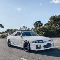
    • small update time, after always wanting a "cool" looking bonnet for my car and always struggling to find one for the series 2 that i liked and wasn't an insane amount of money. Saw one i liked on RHDjapan from D-speed in Japan the price was very good for a carbon bonnet so good infact i was a little unsure how much i trusted it, decided to bite the bullet and with the help of jesse streeter in not long at all it was at my door. Once it was delivered i ran in from work and quickly unboxed it and to my surprise the quality was actually pretty good i quickly removed the old bonnet and placed on the new one to test it out and even the fitment wasnt too bad at all. Then decided to paint the little grille in the bonnet black to stop it sticking out so much.   I decided to not mess around with the hood latch and just install some aero catch hood pins, having never installed them before did some YouTube university classes and i was good to go. fair to say it is not a fun job at all from making brackets so the pins sit nicely and actually cutting through the bonnet but also being very scared of cutting the holes too big it took wayyyy longer than i would like to admit but finally got it there. Then it was time for a quick test drive to ensure the latches actually worked and thankfully the bonnet looked very stable. I still think paint matching the bonnet and leaving just the part that sticks up as carbon would help make it all look alot neater as im not sure how i feel about all that carbon on a very fridge white car but will leave it as is and see how i feel with time.  
×
×
  • Create New...