Jump to content
SAU Community

I'm On A Boat And I Say No To Rice!


toppertee
 Share

Recommended Posts

Also just to note, It looks like production sports cars, are going to allow R32,33 and 34s run in there class. So My Co-driver in the excel cup class and I are going to run the boat in the CUE one hr event next year.

So I'm pretty happy. I can run the car in QR sports and sedans, Improved production (with a turbo choker) and now or soon to be Production sports cars.

It's looking like the skyline is a good choice.

Link to comment
Share on other sites

Righto... continuing the build of the ECU and I'm up to the point where the stock ECU case is now gutted and the connector block desoldered from the original circuit board - I hacked, cut and mangled it pretty bad to get it off the connector, but the end result was good - all the connector pins are healthy and intact.

P1020016_zps3dfff012.jpg

The new MS3 module will fit, but I do need to create some standoff brackets so that it is well secured and pro-like. I could just pack the module with silicone and/or leave it free floating, but I'd like to do this properly and I think a few plastic plates made with the Dremel won't take too long to whip up.


P1020017_zpsf7123342.jpg

Link to comment
Share on other sites

Both brackets made and MS3 Pro module is mounted.

Next step is to think about how to mount USB/Serial connectors for software control, and also think about a secondary connector for things that can't be connected via the stock Nissan connector and harness. I think a trip to Jaycar is on the cards.


P1020019_zpsc879339a.jpg

Link to comment
Share on other sites

Ooh sounds like a project that I'd start and never finish - ending up in a car that doesn't work!

I know enough about electronics to get into trouble...

I admire your skillzzzzz

Link to comment
Share on other sites

Ooh sounds like a project that I'd start and never finish - ending up in a car that doesn't work!

I know enough about electronics to get into trouble...

I admire your skillzzzzz

Which is part of the reason why we've taken to a spare stock ECU and gutted it instead of the original ECU (which only cost under a $100 to source a 2nd hand auto module with the correct harness connectors).

If at any stage we can't get the new MS3 Pro module to work we can fairly easily swap back the stock ECU and with a few minor changes to the intake sensors, be back to working again. The overall goal will be to have MS3 manage custom tune mapped at the dyno with a electronic boost controller making crazy HP. If we have to swap the stock ECU back, it will just mean the engine will run without extra boost and run pretty much like stock. It should be a good solution for getting all the features of a $2000+ ECU system but hopefully come in under $1000 !!

Link to comment
Share on other sites

Oil cooler in

Replaced knacked water inlet pipe on the manifold.

New S/S brake lines

New Discs and MU pads.

New Camber and caster adjustment arms front

Lock out and Camber arms rear

$10 worth on paint on the wheels :yes:

Cage should be here from AGI next week and so should the KAAZ 2 way.

BTW aero bonnet cilps suck balls to install!

IMG_4020_zps265a676c.jpg

IMG_4009_zpsf444405d.jpg

IMG_4021_zps4e173341.jpg

IMG_4022_zpsf29c5eb5.jpg

IMG_4023_zpsa20ecb71.jpg

IMG_4024_zpse7f20873.jpg

Link to comment
Share on other sites

Off the blocks,

Quick drive up the street, all seems good, wife hates it. So it must be cool ;)

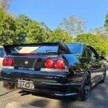
Ride hight is a little low, need to raise it about 20-30mm, I'll have to wait till the coil overs settle. Sold a bit of gear off the car, so I should come in around the 10k mark. Seems like I'm under tired in the rear, with the 225s, I'm having a look for some 9" wheels so I can fit some 255s or 265s. Got to love motor sport, you can spent 100k plus on a motor, but go wider than 9" on a rim and you can't race :rolleyes:

r3330092013011_zpsaa654fd0.jpg

r3330092013012_zps92382cc8.jpg

r3330092013013_zpse5010e0f.jpg

Link to comment
Share on other sites

Cheers,

Really hanging to get out on the track.

I was aiming for the next round of qr sports and sedans. Which is on the 3&4th of nov. I'll be pushing it to make it. Don't really think taking a untested car racing is the best idea. Might have to do a couple of track days and

There is always next year. 1st world problems eh!

Link to comment
Share on other sites

Nup,

I've got to add another axle to the car trailer as well. So there's no hurry at the moment. 1300kg car on a single axle trailer is pushing it.

I'm going to miss the next race meeting.

So I'm going to do testing and get it ready for next year.

Any way I've ran out of parts, so your more than welcome to come over and sit in the paddling pool and drink beer!

Link to comment
Share on other sites

Did some more work on the custom ECU today. Added a USB-B connector (for software uploads and tuning) and a 12V power plug (for bench testing out of the car).

Once the wires had all been soldered in the right spots, I switched her on and uploaded the latest firmware to the board.

Everything went perfect and sweet - next step is to begin the wire-up to the stock connector.

20131011_140808_zps9a984ddb.jpg

Edited by gslender
Link to comment
Share on other sites

  • 5 weeks later...

Well, it's been a while,

I got smashed with work, still pays the bills.

Cars all most complete, off to Ken @ Accurate Suspension, on Monday for the Alinement.

Little update.

The best tool in my shed, under a grand, does the job welds locker diffs, and parts I need for the car. I've never taken a welding course, just a little shed time. I'm no gun but, I've built my own trailer harness point exhaust parts etc. I figure if I hit with a big hammer she's all good in the hood.

IMG_4040_1_zpsedc020f8.jpg

IMG_4044_1_zpsace5e277.jpg

IMG_4047_zps5feb6e16.jpg

I've got stuck into the guages and kill switch this weekend.

IMG_4052_1_zps0d2bd1fb.jpg

IMG_4049_1_zps3c103fbf.jpg

New 2 way diff

IMG_4048_1_zps3b12b6be.jpg

Bumped into a bloke off loading his race wheels and tires, 295 35 R17, should grip!!

IMG_4055_1_zps8e18b42b.jpg

I bitter that I missed out on running last week, so next date is going to be on the 14th Dec @ QR for a sprint meet, fingers crossed.

Just got to add a extra axle to my trailer, don't like the idea of a 1300kg car on a single axle.

Link to comment
Share on other sites

Cheers

Grants popping over this weekend, we are hopeful the ms3 is going to fire.

Also found out the front of the car has taken a hit in the past,slightly bent driver side . So I'm having the front camber arm machined. To allow for a little more camber on the driver side. To straighten up the alinement.

Can't wait to get it on the track.

Looking forward to a little dickyspeed master action ;-) I'm going to be pretty slow, I've not had a drive for about 6 months.

Link to comment
Share on other sites

Mad soldering skills!

I'm not drinking tonight, so I won't be hung over. Think this will be the first time we've worked on a car, with me been sober!

Don't know wether that is a good thing or a bad thing, haha.

Can't wait to start logging data again, I'm really missing tuning studio!

Link to comment
Share on other sites

  • 2 weeks later...

Well the MS3, went into full fail boat mode!

So we are going to leave it for a xmas build, while we have a rethink. I.E. read the bloody RB25 circuit diagram. So screw nissan

and there ECCS relays!

Should be all good. What we are trying to do, is use the standard loom and make it plug and play with out cutting into the stock

loom to much, when I say we, I really mean Grant! I'll take to a supercar with a angle grinder.

r3324112013022_zpsf7b1e480.jpg

Link to comment
Share on other sites

Create an account or sign in to comment

You need to be a member in order to leave a comment

Create an account

Sign up for a new account in our community. It's easy!

Register a new account

Sign in

Already have an account? Sign in here.

Sign In Now
 Share


  • Similar Content

  • Latest Posts

    • The two diagrams are equivalent. The R32 one is just one sheet out of about 3 showing everything in the whole car all at once. And without knowing the functionality that occurs in the modules, they are both equally opaque.
    • 8v - 2.48ms 9v - 2.15ms 10v - 1.74ms 11v - 1.41ms 12v - 1.15ms 13v - 0.99ms 14v - 0.89ms 15v - 0.82ms 16v - 0.81ms I'm running these values on my RB20 Neo with 570cc Denso R35 stock jets and it's great. Also bought a set for my Legnum VR4, love these injectors!
    • Thanks for your reply,  Those blue/green wires running to the actuator aren't attached to anything, so I'm not sure how the central locking is still working. I will have to take a good look tomorrow, I don't have the car with me. After googling it seems like a pretty common aftermarket actuator which even uses the same green/blue wires the immobiliser required. i'll test everything tomorrow and if it's working i'll melt the solder, strip it, resolder and neaten it all up with some heat shrink. I don't have to understand it if it works hahaha I just don't want a fire/ short circuit. That R32 diagram looks more like a continuity chart? Can you make sense of this form the R34 manual? 10V is probably due to very flat battery, i'll recheck as well tomorrow, I did have to jump start it haha. Thanks again!  
    • So, COM doesn't mean comms. It means common. What common itself means will depend on the type of device. For a two directional actuator (ie, one that can push and pull on the same output rod) then the common will typically just be the earth connection. There will be at least 2 other wires. If you put 12V on one of the other wires, then the actuator will push. On the other 12V wire, it will pull. Can't quite make out what is going on with the wiring of your actuator. It appears to have several wires at the actuator plug, but there only appears to be 2 wires where its loom approaches the door control module, with at least one of the others cut off. I don't know these actuators off by heart. I'd have to look at a wiring diagram for one before knowing what the wires were about, and that's despite me having to replace one in my car not all that long ago. Just not interesting enough to have dedicated memory set aside for trivia like that any more. That actuator is an aftermarket one, not the original one, which probably died and was replaced. That might require some sort of bodge job on wiring to make it work. Although nothing should justify the bodginess of the bodge job done. As to the soldering job on the door module's loom plug. Ahhahhahaha. Yes, very nasty. Again, I cant tell you what any of those wires do. You'd need to study the R34 wiring diagram (if you can find one that shows the door module). I don't think I have any. I'd have to study the R32 diagram to start to understand what mine is doing, and again, even though I've had a problem with mine for the last 25 years (where it locks the passenger door when the driver's window reaches top or bottom of travel) I'm just not interested enough to try to to work it out. So long as it's not burning down, it's fine with me. Here's the R32 GTR diagram, which, confusingly, has rear door lock actuators and window motors on it!! As you can see, unless you understand the functions of the door lock timer and the power window amplifier, you'll never be able to work out how it works just from the diagram. I don't imagine that the R34 one is any better. Hopefully an R34 aware bod can help. FWIW, the two wires that are cut and joined look like they are both power supply - so hopefully it is not fatal to join them. The 10V you measured on the cut off free end of one of them is concerning. You'd expect 12V, and it might be the reason for the bodge job joining them together.
×
×
  • Create New...