Jump to content
SAU Community

Recommended Posts

Many of you will have read about my RB31/RB315 project. This project is the next stage of development.

While this new engine's predecessor, (the version 1/2 engine) worked, it had few design shortcomings. There were some build execution issues that could have caused some potential longevity issues. There was also the machining cost issue, that would have prevented the design from ever being able to evolve into a marketable product. Too much custom componentry modifications were required to complete the engine. These things made the engine overly complicated and costly to build to completion.

The new engine design resolves these issues. It uses more off the shelf components and require less modification of supporting parts (exhausts, intakes, plumbing cylinder heads etc). I also wanted to reduce the cost of machining, and massively improve the strength of the design. The version 3 design does all this and raises the bar significantly in other ways.
A little over 2 years of R&D later I can now make public the completed new engine design. Broad strokes of the design are as follows:

  • Nissan RB26 024U or 05U block can be used.
  • New spacer plate design, 6160 billet alloy
  • New cylinder sleeve design which supports cylinder bore sizes up to 90mm
  • New gasket system for the spacer plate
  • New head gasket design
  • Off the shelf ARP2000 12mm or ARP CA625 studs

The block and sleeve designs have undergone FEA to identify stresses that are caused by assembly, combustion pressures and also thermal expansion variations.

Along with these changes the machining processes have been completely re-worked. This has been done to reduce the manufacturing costs, but the main reason is to achieve the necessary tolerances to take the engine design to the next level. The entire engine is now 100% CNC machined, and as a result the design can now be mass produced.
In keeping with the original concept, the engine is still designed to be streetable. Although the extent of that will be greatly determined by how wild the cam and cylinder head configuration is that would be fitted to the engine.

The v3 prototype engine that has been built in the first of the v3 blocks pushes a few more boundries. The engine is quite possibly the first 3.4lt RB26 based engine ever made. Full specs are as follows:

  • RB34/24U - 3.4lt (3360cc)
  • Open Deck Engines V3, 20mm Open Deck spacer plate block
  • Custom Nitto 90mm crankshaft, with SR20 rod journals
  • Nitto SR20 h-Beam rods, with custom oil jets
  • Nitto/JE Pistons, 89mm bore size, 8.9:1 compression
  • Tomei Oil Pump
  • Tomei Complete Step 2 head (Tomei manufactured head will all their top shelf parts)
  • High Octane sump
  • Greddy Intake plenum
  • Full-Race twin scroll / twin gate manifold
  • Two Tial v-band gates
  • Precision 6466 CEA twin scroll turbo, 1.00 housing
  • Custom 4" turbo back exhaust, to 90mm trust titanium exhaust.

The fuel system, ECU and electronics are currently the same setup as per the V2 engine so as to allow the engine to be started and run in quickly. They will be upgraded in time once the run-in is completed.

The engine was started for the first time today. It is running a little rough when the throttle is cracked open as it wants a lot more fuel. I've since fattened up the map a little and it now seems ready to put on a dyno for run-in and testing.


Here are a few pictures and video of the engine running.

http://www.youtube.com/watch?v=lT1Hm-o5SsE&feature=related


The complete build will be posted over the next few days. I have a huge library of photos to review.


I still need to bleed the brakes and clutch, put on the ac and power steering belts, change the tyres, and put the inner guards and front diffuser back on the car, so there is a fair bit to do before it's driven.

Cheers,
Ian Swinkels

DSCF0834 - Copy.JPG

Copy of IMG_0969.JPG

  • Like 3

Here's a video that works: http://www.youtube.com/watch?v=lT1Hm-o5SsE&feature=related

Hopefully one of the mods will be able to update the first post, and allow me to edit it so its a bit more readable. Something went wrong (like me posting the thread near midnight), and all the paragraph formatting was dropped.

  • Like 1

So Update!

I put the rest of the car back together today, bled the brakes and clutch, fitted belts, filled power steering and put on the front aero parts again. The only thing that remains is connecting a little wiring for the thermo fan controller. Fitted the TE37's again too, now wearing new Federal 595RSR's.

So back to the build.

I decided to build this engine into a new 24U block. There was a few reasons for this. In part I wanted to build something special for my car, and the 24U block adds to this. But I also wanted to use a 24U block so I could really see the differences between a 24U and a 05U block.

During the process of converting the block to an open deck engine, a lot of material is removed from the block before the block sleeves are installed. I was going to be able to see exactly what the internal dimensions are with the 24U block.

All machining of the block has been performed in a Centroid 5 axis CNC machine. The entire block has been digitalised, and a program developed to allow the design process to be repeated easily.

Out of the box, the 24U block isn't really that impressive a block. The cylinder bore centres were up to 0.015" off from the correct centre of the crankshaft rod journals. To correct this the block was initially bored to 88mm so as to not have an intermittent or un-even cut happening when the sleeve boring program was run.

post-26553-0-05653500-1383644352_thumb.jpg

Once the block is setup in the machine, the block is digitised to allow the cylinder bores to be re-positioned. The spacer plate is then bolted on, along with a drill guide plate. The drill guide plate is a 3mm thick mild steel plate which is dimensionally accurate for what will become the finished engine.

The machine first machines the head alignment dowel holes.

post-26553-0-41323400-1383645191_thumb.jpg

post-26553-0-70602700-1383645410_thumb.jpg

Edited by GTRNUR

The block is then machined for the sleeves as one unit with the spacer plate and drill guide plate installed and torqued to spec. The softer alloy spacer plate is protected from swarf damage by the drill guide plate, and at this point the whole shebang is doweled together as well.

The sleeves are shrunk in a freezer prior to being installed, which allows the sleeves to be worked with a little to achieve correct interference fitment. The sleeves are also chemically bonded to the engine block when they are being fitted.

The new sleeve design is simular in outward appearance to an OS giken engine, but that is where the similarities end. The sleeves have multiple outside diameters, each with a different interference fit. The flanges at the top are also not only keyed together, but shimmed appropriately so as to eliminate a stress concentration that would otherwise exist due to thermal expansion and combustion pressure forces. Such forces would otherwise cause a fatigue induced failure been the cylinders.

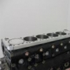
As you can see from the second picture attached, the sleeves at this point extend past the spacer plate. This plate at this stage of the machining process was 20mm thick. The sleeve are 22mm tall past the deck height.

post-26553-0-97370000-1383646594_thumb.jpg

post-26553-0-47400000-1383646742_thumb.jpg

Is there a round about figure on cost for a bottom end package?

It will be about $13-14K for a completed block, with spacer plate, main and head studs, long dowels, and spacer plate gaskets. Its not much more expensive than an RRR block, but is obviously a lot more engine as you will soon see.

I'm still a long way from that though. More testing is needed.

Once the block has been sleeved, the coolant galleries are then partially filled with a composite resin. This block has been filled to 1/2 way up the welsh plugs.

Final block boring and honing can then be completed. The base sleeve design has an 87.5mm raw bore inside diameter. The sleeves can be used as 87.5-88mm with a conventional stock or aftermarket gasket. Larger bore sizes require custom gaskets. The sleeves will support up to a 90mm bore.

This completed block has an 89mm bore size and is setup to use a copper head gasket. A pre-assembly of the rotating assembly was performed in order to determine the correct height of the sleeves, and they were then trimmed back to suit the application and target compression ratio. Final block height was extended 20.8mm in this case, and the target compression ratio was 9:1 with a 1mm head gasket.

The tops of the sleeves have a receiver slot as well, to help further improve the seal with the copper head gasket. The cylinder head has a matching o-ring configuration. When torqued to spec the copper head gasket is deformed into the receiver slot creating the ultimate cylinder seal.

Last of all from the under-side, this block has also been clearance for the 90mm stroke Nitto crankshaft. Future versions of this will not require such clearancing as the cranks will be manufactured to suit the block. The clearance of the cylinders for the rods was also necessary to ensure 0.090" clearance to the rods when the crank is at 90 and 270 degrees.

That's all I have time to post tonight.

post-26553-0-76673200-1383649028_thumb.jpg

post-26553-0-82658200-1383649104_thumb.jpg

post-26553-0-82919800-1383649318_thumb.jpg

Edited by GTRNUR

Really keen to learn how this is going to turn out.

Well done so mate. Looks very similar to OS Giken 3.1 kit but I know theres a lot more to it than.

subscribed as well

Well here is where the differences become noticeably different to an OS engine.

First off, to lower production cost I had to change to an alloy spacer plate. The steel plate used on the V1 engine cost not much under $2k to produce (water jet cutting, surface grinding etc), and to be honest even after that it was not even remotely close to being an impressive looking thing.

The one thing that a steel plate has going for it is that it expands at the same rate as the cylinder sleeves do. This means the plate will not try and lift the head off the top of the cylinder sleeves (resulting in a blown head gasket), as the engine heats up. Alloy would normally do this. Over the full operating range of the engine, the spacer plate will grow at least 1.1 thou thicker due to the thermal expansion coefficient difference between alloy and steel. This issue aside, it is softer so as a result it is much cheaper to machine quickly. This opens the door to use CNC machining to produce a far superior plate design.

The current plate design has gone through 7 revisions to get to where it is now. I was very lucky to track down an Australian company called CNC industries, who were able to produce prototype plates for me cheaply. They did so with 3 weeks turn-around for the first plate, and considering that was manufactured and shipped from China that is an amazing effort. The quality of the plate is amazing too. From the top the plate resembles an RB26 block, but the under side is scalloped out around the sleeves to permit coolant flow around the upper deck. The reasoning for this is to maximise cooling area, while also providing the best possible supporting layer for a head gasket.

I've had 3 plates so far. One has been used in this current build, and the two others will be hopefully used as well inside the next 3-6 months.

As you saw from the block machining, the spacer plate is bolted to the block early in the process. During the sleeving phase, the plate and the block become a matched set. Initially located to the block with dowels, but finally also by the precision with which the sleeve holes are machined into the plate. The whole assembly locks together absolutely perfectly.

post-26553-0-58765500-1383720183_thumb.jpg

post-26553-0-09985700-1383720226_thumb.jpg

post-26553-0-93767300-1383720247_thumb.jpg

post-26553-0-97038700-1383720269_thumb.jpg

post-26553-0-19946900-1383720497_thumb.jpg

Edited by GTRNUR
  • Like 1

Create an account or sign in to comment

You need to be a member in order to leave a comment

Create an account

Sign up for a new account in our community. It's easy!

Register a new account

Sign in

Already have an account? Sign in here.

Sign In Now


  • Latest Posts

    • does anyone know tie rod torque setting and anti roll bar for r34? Is there a workshop which shows various components torque setting?
    • Hi    have purchased pair of eibach wheel spacer as I couldn’t fit set of wheels I bought for my car due to it catching caliper.   I know I need to cut the bolts on my discs so they sit flush with the nut supplied but the nut doesn’t sit all the way into the groove meaning wheel would not directly fit onto the spacer rather the nuts. Any thoughts?   See pic   https://ibb.co/VJK5w5G
    • Nah. There's not shit tonnes of pressure in there. Just drill with a 1.5mm drill or something equally tiny. When the drill goes all the way through thee gas will start to come out, but with such tiny path through the flutes of the drill bit, it won't be at all dangerous. You can be as paranoid as you like from then on. I'd just pull the drill out while keeping my face out of the line of fire. But then, I spend half my time looking into pressurised furnaces. So my risk acceptance is somewhat higher than most!
    • Been needing a new clutch for a while, but holding off because of life tingz and adulting. But... Being of Asian descent, I can't pass on a good sale, especially everyone else is selling it for $2k+ (JJR has it for $1799). Really on the fence on this one, because the unsprung version of this is $1281 via Shitbox (Sparesbox) and the sprung version is quite a bit more (no idea why Shitbox doesn't offer them). Ending up just sending it and getting the twin sprung organic. Mainly because I wanted the car to be nice to drive and didn't want to make it more of a shitbox than it already is.    
    • It was the pressure I was worried about. @GTSBoy does drilling them pose any problems?
×
×
  • Create New...