Jump to content
SAU Community

Recommended Posts

1 hour ago, GTRNUR said:

Yes some progress has been made.  All parts to complete the next two engines are in the hands of the machine shop awaiting final machining.  If things are completed on time I'll have everything ready to assemble the "insane spec" RB33 next Friday. The RB32 that will follow will be a few more weeks after that.

I changed my business name to Project RB recently too, and dropped open deck engines as none of the new engines are open deck anyway.

I completed a 900km day trip about in the car about a month ago and have been driving every day that I can when its not raining. I believe there is about 16,000km on the new setup now.  The long road trip revealed that my alternator can't keep up with the rest of the higher than normal electrical load in the car, so I've got a 150A alternator upgrade going in soon.

That's about all.  Fingers crossed for no more delays.

Had the same problem with my alternator, after charging my battery it would slowly loose the charge, high beam would not work, MFD would go blank, installed a 150A Black and no more flat battery :)


5 hours ago, NISR32.5 said:

Nice work mate. Looking forward to some pictures and updates on the new motors.
Any reason for dropping the open deck design?

The version 1 engine which was a 3.15lt (87x87.5) was an open deck design, where coolant could surround the entire top of the cylinder liners.  While great for cooling, this also meant the top of the cylinder could deform due when under high cylinder pressures. 

The RB34 is a closed deck design, with an aluminium spacer which supports the tops of the cylinder liners, but reduces coolant flow around the tops of the cylinder liners. 

The RB33 currently in production is a further improvement on this design, using a steel spacer plate system with internal coolant galleries and no coolant flow to the cylinder head.  The matched cylinder head has all the coolant galleries from the block CNC machined and plugged as well, such that no coolant flow enters the head via the block.  Coolant is delivered to the head via an external connection, and drawn out via the plenum coolant manifold. 

This allows the engine to use a copper head gasket with no long term fears of having gas escape into the cooling system.  It also eliminates any chance of a cooling system leak/explosion as a result of the cylinder head lifting under very high power use.  Not that there is really much chance of this given the 5.6" long ARP625 studs, but when aiming for 1500hp I'm not taking any chances.

5 hours ago, Nismo 3.2ish said:

Had the same problem with my alternator, after charging my battery it would slowly loose the charge, high beam would not work, MFD would go blank, installed a 150A Black and no more flat battery :)


That's pretty much how it went.  My long drive started before dawn, and ended 14 hours later after dark.  Using headlights on the way home put the charging system over the edge. After I got home I tried to re-start the car and only the pumps would run.  Not even a solenoid click on the starter.

I've made some changes to the PWM control for my cooling fans now though, such that when they are turned on their speed is PWM throttled back as vehicle speed increases.  Eg, at 70km/h the cooling fan switches off completely as airflow is adequate at that point.  Twin in-tank walbros are still PWM speed controlled linked to injector duty, so at cruise speeds the OEM alternator would probably be enough now.  But I've never been happy with how the OEM alternator has always seemed to struggle.  The 150A alternator is certainly going to remedy that.

Edited by GTRNUR
45 minutes ago, GTRNUR said:

The version 1 engine which was a 3.15lt (87x87.5) was an open deck design, where coolant could surround the entire top of the cylinder liners.  While great for cooling, this also meant the top of the cylinder could deform due when under high cylinder pressures. 

The RB34 is a closed deck design, with an aluminium spacer which supports the tops of the cylinder liners, but reduces coolant flow around the tops of the cylinder liners. 

The RB33 currently in production is a further improvement on this design, using a steel spacer plate system with internal coolant galleries and no coolant flow to the cylinder head.  The matched cylinder head has all the coolant galleries from the block CNC machined and plugged as well, such that no coolant flow enters the head via the block.  Coolant is delivered to the head via an external connection, and drawn out via the plenum coolant manifold. 

This allows the engine to use a copper head gasket with no long term fears of having gas escape into the cooling system.  It also eliminates any chance of a cooling system leak/explosion as a result of the cylinder head lifting under very high power use.  Not that there is really much chance of this given the 5.6" long ARP625 studs, but when aiming for 1500hp I'm not taking any chances.

1500hp is crazy.

What snail/s are u going to run and what will be the application for this engine, drag?

40 minutes ago, Piggaz said:

More pumps, more gauges, more, more, more. Everyone forgets about where all this "more" is coming from.

If only I had night vision...  Like the Japanese Starion entry in Canonball run 2.

27 minutes ago, Marko R1 said:

1500hp is crazy.

What snail/s are u going to run and what will be the application for this engine, drag?

Precision 88mm +, and street.

  • Like 1
  • 1 month later...
12 hours ago, Ecozile said:

Really good read - all of the 13 pages. 

Anything else on this space? 

One of the two current builds is complete and should be up and running in a car in 3-4 weeks.   

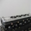
This is the RB33 with my version 8 spacer plate, which isolates head and block coolant flow.  89.8 stroke x 88mm bore. Isolation prevents combustion gas getting into the coolant system.  Head o-ring and block o-ring receivers are the same as the RB34.  This block has some substantial strength upgrades though in the form of the steel billet main caps and girdle plate, 12mm main bolts, ARP 625+ bolts through-out, and a tall block/coolant gallery fill (not grout, but with an engineering composite). 

The RB32 is currently in the CNC mill may be a few months still.  It uses the same spacer setup as my RB34, with the addition of a platinum racing girdle plate instead of the pro engines girdle.  The main benefit being that a OEM positioned oil pump can be retained as tunnel boring is minimal, where as the RB33 must use an external pump due to larger clearances.

14191346_10153986817762462_1781755526_o.jpg

14215592_10153999455292462_1940524529_o.jpg

14087639_10153967449877462_680195018_o.jpg

IMG_1109.JPG

14112003_10153967449982462_1766372363_n.jpg

  • Like 2

Very well done!

Have you put thought into or is it possible through what you have learned to achieve an 88mm bore on a stock stroke RB26 (with addition of sleeves), or other methods to improve strength at that bore size?

35 minutes ago, bigmikespec said:

Very well done!

Have you put thought into or is it possible through what you have learned to achieve an 88mm bore on a stock stroke RB26 (with addition of sleeves), or other methods to improve strength at that bore size?

Hi Mike,

The sleeve design still requires a spacer of some sort to support the flanges at the tops of the sleeves. 

Consider the Darton Rb26 dry sleeve kit.  They recess 5mm of flange thickness into the upper deck of the engine.  When you consider the OEM thickness of the upper deck is not all that thick to begin with, this puts their outer diameter of the top flange VERY close to the coolant galleries.  The only way to get more bore thickness is to run a thicker flange and thicker sleeve OD below the flange, meaning significantly more OEM deck and bore material is removed.

The high deck sleeve approach retains deck integrity by not machining material from the OEM deck, and instead sits the flange on top of that OEM deck, vertically supports the deck from stresses due to the interference fit of the base of the sleeve into the material in the block between the mains.

The risk of removing supporting material in the OEM deck is that the deck will probably crackwhen the head studs are torqued up.  Consider how torqueing head studs distorts a cylinder bore, it does equally horrible things to the cylinder deck surface. Especially with studs that hold 125-150ft-lb like the ARP625's.   Head stud anchoring material is both under the stud supported by the sides of the block, and also across the top of the OEM deck.

As I see it, you would need to have 10mm of flange/plate thickness at least. 

Do you have an expected timeline as to when these will be available for purchase, either publicly or to early adopters/testers? I was looking at RB30 options but I'm thinking an RB34 might just be what the doctor ordered.

I'm across the pond in Canada, currently in the planning stages of a full-race R14 build, and shooting for something in the 500kW/675whp range.

Edited by wakawakalj
On ‎23‎/‎09‎/‎2016 at 9:59 AM, wakawakalj said:

Do you have an expected timeline as to when these will be available for purchase, either publicly or to early adopters/testers? I was looking at RB30 options but I'm thinking an RB34 might just be what the doctor ordered.

I'm across the pond in Canada, currently in the planning stages of a full-race R14 build, and shooting for something in the 500kW/675whp range.

At this time there is only one more build in progress, and it is an RB32 (87.8 x 88mm), not an RB34.  But it should be ready in a month or 2. 

I have made some changes to the design as well (again), due in part to the rapidly rising cost of the 24U engine blocks.  Frankly $5300 AUD is completely out of control for an engine block.  They are not that special, and when you consider how much I machine out of the block anyway they aren't worth it.  So to bring the costs down again I am building the next engine into an 05U block, with identical sleeves and spacer plate to the first RB34 plus the addition of ARP2000 mains and a platinum racing girdle plate.

I've also changed the grout-filling method.  I'll be filling the lower section of the block with hard-blok and then cap it off with industrial composite resin.  This instead of completely filling the block with resin will reduce costs a little and be just as strong.  The resin cap will prevent grout erosion and blocking of coolant galleries over time. 

I've been able to make some great industry contacts over the past 12 months.  As such all engines will be using Carillo rods and billet crankshafts made to order by a manufacturer of Pro Stock crankshafts in the US.  Ironically this works out cheaper (and better) than re-engineering a Nitto crankshaft, even with the exchange rates.

Depending on how the next round of testing goes, I will be looking at doing a production run of 5 x RB34's.  Fingers are crossed for the future.

  • Like 5

That's excellent news. I'd really like something in the region of a 89-89.5 x 90mm setup, as I want to badge the car as a 340z when I'm done.

I'm a mechanical engineer and love the work you've done. I'm really looking forward to watching this progress. It should be pretty ridiculous with a VCT setup and something like an EFR 9174/9180. I was initially looking at using a progressive nitrous pre-stage solely to spool the turbos, but with an extra 800cc + VCT it should be completely unnecessary.

  • Like 1
  • 3 months later...

So it turns out the last block I machined had been in a car accident, and event though dye penetrate tested a crack next to the engine mount was not found until the engine was started and the leaking of fluids began.  :(

I've been madly sorting out a new spacer plate, have purchased a new N1 block, sleeves etc, so I can prepare a new block and transplant all the components for the RB33 pictured above.

I have an RB32 in an 05u block with a platinum racing girdle ready for assembly.  This will most likely also end up as a "test" engine, as I need to evaluate the reliability of an 05U block after it goes through this conversion process. 

At this stage I still do not know when a sales/production run will be done.

IMG_1253.JPG

  • Like 2
  • 5 months later...

There has been big developments with the project.  Towards the end of June I completed and delivered the rebuilt RB33.  It has been run a few times and initial indications are that it should perform very well.  The engine is in the process of being installed in a new car, and should be driving in just a few weeks.

I re-designed the entire sleeve and spacer system for the revised RB33 to increase its overall strength.  The new spacer is now made from alloy like the RB34/v3  design. 100% CAD/CAM manufactured, and uses o-rings for all sealed surfaces.  Gasket-less seals make for a more stable upper deck and more overall block rigidity.  

The spacer and sleeve system are is now a Siamese cylinder arrangement, and are interference fit/assembled using a somewhat complicated method using hot tanking and dry ice. This process makes the effective upper deck and sleeve thickness achieved with the extension much thicker and stronger than before.  

I was able to retain some of the OEM oil returns with the new setup, although the RB33 build is using a 2 stage external pump/wet sump setup which incorporates a scavenge stage as part of the method for extracting oil from the head.   The cooling systems for the head and block are still isolated with this new design, with coolant extraction through the spacer plate, and externally plumbed coolant flow to the head. 

I can't wait to hear the engine run again. You can be sure that a lot of video will be posted when it does.


IMG_1534.JPG

IMG_1586.JPG

IMG_1593.JPG

  • Like 8
  • 1 month later...

Create an account or sign in to comment

You need to be a member in order to leave a comment

Create an account

Sign up for a new account in our community. It's easy!

Register a new account

Sign in

Already have an account? Sign in here.

Sign In Now


  • Latest Posts

    • If doing that ^, I'd take the idle up valve out and plug the hole in the pump.
    • You can try capping the power steering idle up valve at both ends if it's old. The valve and the intake manifold. That is something that is known to fail in Toyotas with age and it will suck power steering fluid into the intake and burn it in the engine which can cause issues. Then bleed it again with engine off first. Do like 30+ lock to lock turns with the front wheels off the ground.
    • Hi Brent, I am wondering if you ever worked this out? I have upgraded this unit to a newer one and everything works bar the reverse camera, so i really want to know what plugs are what so I can patch the camera through. many thanks in advance Mike
    • Once you have to get up in the morning and be useful, you suddenly value sleep it turns out :p
    • Update:   smoke test all pipes no issues cleaned reservoir   fluid put in ( dexron 3 atf)   steering turn side to side and could hearing  gurgling from steering rack which I assumed was air lock, opened one of the steering rack connections and could see loads of air getting pushed out( not sure if you meant to do that / whether it will re introduce air into system)   anyways, loads of side to side sound was gone. Turned car on, pump was slightly ( barely) wining so turned side to side few more turns and fluid level when car on was almost none in resorvoir which I guess is normal if car is one. Turned car of and fluid was gushing out. Almost 200-300cc was pushed out. Repeated engine off side to side followed  by engine on and same result       going mad now. It seems system is either sucking air in whilst on or there is tons of air which I am not giving it enough time to bleed. Thoughts?   would it work like brake caliper if I open steering rack copper pipes and let gravity pull all air out?   or maybe have a restriction somewhere? What is the red circled item, could that be blocked? It i
×
×
  • Create New...