Jump to content
SAU Community

Recommended Posts

Hey guys,

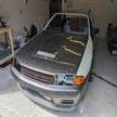
Just received my carbon bonnet which has a scoop for the air intake

post-68489-13896052238974_thumb.jpg

And now need to make a POD box. It's simple enough to make a normal box such as the one found in this thread. http://www.skylinesaustralia.com/forums/topic/208224-making-a-professional-heatsheildpod-coverair-box-at-cost/

But I want to make one that has a seal around the bottom of the bonnet (top of box) where the scoop is to make sure the air is going where it should. I would think for this that I would need to form a compressive rubber seal the bonnet can sit on but unsure how to go about actually measuring the heights needed around the box walls to keep the seal on the bonnet??? I mean it's pretty hard to close the bonnet and see how high the walls and then rubber lining needs to be??

Any help would be greatly appreciated.

-Dallas

Sent from my iPhone using SAU Community

Basic idea:

Make the box in the general area of the scoop. Put some sort of thick/tall lining around top of box with some paint on it. Make sure itll touch the hood when u close it. Close hood, and you will get imprint on hood. Place Some foam on top of box and on hood where the paint outline was so that they press togethor when hood is closed.

Thanks I'll give the foam a go on top of the box then cut it so all edges are touching the hood with roughly the same force then I'll have the print for a rubber seal. Might use chalk so I can remove it from the hood and have several goes at getting the seal right on each edge.

Sent from my iPhone using SAU Community

I did a similar thing with mine.

I got the Perspex from bunnings (u can cut with a grinder or anything really) and the rubber edging from clark rubber which I glued onto the Perspex with sikaflex.

cut the Perspex to the required shape to make an airbox that basically seals against the bonnet (1-2cm of clearance) and then use the rubber edging to complete the seal.

Bottom line is you are never going to get a perfect seal so a good job will do 99% of the effect desired. The main intent is to block the air from the engine bay and make the easiest air for it to breathe from the cold air entry.

Edited by jjman

I made this setup for a 550kw Supra, force fed from the front bar by a 4 inch pipe. It used to lift the bonnet slightly at high speed so the seal must have been pretty good.

I used flat alloy sheet with heat proof foam backing, and the Clark rubber seal.

post-63525-0-81661800-1389704377_thumb.jpg

Hey guys,

Just received my carbon bonnet which has a scoop for the air intake

attachicon.gifImageUploadedBySAU Community1389605220.829911.jpg

is this a full carbon fibre bonnet or a fibreglass with a layer of cf over it?

I have the same bonnet in fibreglass. but if I can find a full carbon fibre one I would like to upgrade, I have a arc airbox that sits perfectly under the scoop, been wanting to make a duct for it, post up photos of how you go with this

Attacked it this afternoon. Got the box done and the seal with a foam cut out. The foam still needs a bit of trimming to fit perfect and look a bit cleaner but I'm happy with how it's gone so far

post-68489-13901060001973_thumb.jpg

yeah id say sand it to a smooth texture if possible n then spray.

even then, iv heard that the test most cops like to try is the grab n pull. if they do this n shit moves or breaks off they are likely to give the defect. You think it will stand up to that?

Create an account or sign in to comment

You need to be a member in order to leave a comment

Create an account

Sign up for a new account in our community. It's easy!

Register a new account

Sign in

Already have an account? Sign in here.

Sign In Now


  • Similar Content

  • Latest Posts

    • Yep, pretty much what you said is a good summary. The aftermarket thing just attached to the rim, then has two lines out to valve stems, one to inner wheel, one to outer wheel. Some of the systems even start to air up as you head towards highway speed. IE, you're in the logging tracks, then as speeds increase it knows you're on tarmac and airs up so the driver doesn't even have to remember. I bet the ones that need driver intervention to air up end up seeing a lot more tyre wear from "forest pressures" in use on the highway!
    • Yes, but you need to do these type certifications for tuning parts. That is the absurd part here. Meaning tuning parts are very costly (generally speaking) as well as the technical test documentation for say a turbo swap with more power. It just makes modifying everything crazy expensive and complicated. That bracket has been lost in translation many years ago I assume, it was not there.
    • Hahaha, yeah.... not what you'd call a tamper-proof design.... but yes, with the truck setup, the lines are always connected, but typically they sit just inside the plane of the rear metal mudguards, so if you clear the guards you clear the lines as well. Not rogue 4WD tracks with tree branches and bushes everywhere, ready to hook-up an air hose. You can do it externally like a mod, but dedicated setups air-pressurize the undriven hubs, and on driven axles you can do the same thing, or pressurize the axles (lots of designs out there for this idea)... https://www.trtaustralia.com.au/traction-air-cti-system/  for example.... ..the trouble I've got here... wrt the bimmer ad... is the last bit...they don't want to show it spinning, do they.... give all the illusion that things are moving...but no...and what the hell tyre profile is that?...25??? ...far kernel, rims would be dead inside 10klms on most roads around here.... 😃
    • You're just describing how type certification works. Personally I would be shocked to discover that catalytic converter is not in the stock mounting position. Is there a bracket on the transfer case holding the catalytic converter and front pipe together? If so, it should be in stock position. 
    • You talking about the ones in the photo above? I guess that could make sense. Fixed (but flexible) line from the point up above down to the hubcap thingo, with a rotating air seal thingo. Then fixed (but also still likely flexible) line from the "other side" of the transfer in the hub cap thingo up to the valve stem on the rim. A horrible cludge, but something that could be done. I'd bet on the Unimog version being fed through from the back, as part of the axle assembly, without the need for the vulnerable lines out to the sides. It's amazing what you can do when you have an idea that is not quite impossible. Nearly impossible, but not quite.
×
×
  • Create New...