Jump to content
SAU Community

Recommended Posts

Was at the track a few weeks ago and kept blowing intercooler hoses off at each end. Managed to do a bandaid fix at the track, but what's the most effective way of securing them?

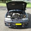
The hoses themselves appear to be in good condition, but the clamps were a bit old and loose. Would a high strength clamp like the one pictured do the trick?

What about hard pipe kits? Are Just Jap's any good? From the photos the bends look fine but the clamps themselves don't appear to be of very good quality.

What are some other methods of keeping them secure?

NCL_GBS_STC.jpg
Link to comment
https://www.sau.com.au/forums/topic/437821-blowing-intercooler-pipes/
Share on other sites

Best way to do it one is get some sprinb tension clamps all that bulky t bolt stuff is rubbish. Heres what i use

http://www.norma.net.au/products/hose-clamps/norma/norma-constant-tension-hose-clamps

Very well priced nice and compact and will not come off. Also make sure all pipes have a lip at the end of them.

worm drive hose clamps arent that good, I use the ones as posted in the first post, or similar ones and have no problems at all with them. Running 24psi now and no issues

Make sure to clean the pipe and the silicone joiner with wax and grease remover or something like that so that there is no oily residue etc on them. A nice bead on the end of the pipes will do wonders but some of my pipes don't have these and work alright with the good clamps and a good clean.

What have you got in it? Still standard hoses? If so might be a good time to get some silicone joiners just to refresh the old ones (If they are original)

But if they are still nice and soft then there is problably no issue with them.

Normal clamps were the bane of my existence until I bought a bunch of the ones shown in the pic in the first post. I haven't had issues since even without beads on some pipes.

Another thing to consider is make sure you don't have any load on the pipes ie:get it all sitting nicely first then tighten them.

Can't say I ever had a problem over 3 cars/8 years and always over 20psi with standard clamps/Norma style ones.

Often you'll find a bit of oil gets onto the cooler pipes, ensure you give them a good cleaning off first and that sometimes can make all the difference with stopping things moving too much.

Also as stated, check engine mounts. If things are moving around too much that will also cause you to pop a clamp off a lot more easily.

I've been using marine grade clamps. They are the same basic design as any clamp, but better quality.

When joining two hoses together with just a short bit if pipe I use 2 hose clamps. One on each hose, and then I cut the third clamp into short lengths of stainless material and have the two clamps spot welded together at the required distance. This works great and still allows a lot of hose movement without any leakage.

If my explanation isn't too good I can post up a picture tomorrow.

Are you saying that you put 2 clamps in then weld parts of a 3rd clamp between the existing 2?

if so..... why?

When two clamps are joined together and are put over a join, hose movement and pressure can't blow the join apart as the straps hold the hose together. Especially useful over short joins. This join held 30 psi no problems. There is no lips on the join either, its just a straight piece of pipe.

I am not a fan of bolt on hose clamps like those above. They can distort the hose when clamped, pinching it where the clamp closes up diameter and result in an air leak there because of it.

post-26553-0-21495400-1390338514_thumb.jpg

Edited by GTRNUR

Create an account or sign in to comment

You need to be a member in order to leave a comment

Create an account

Sign up for a new account in our community. It's easy!

Register a new account

Sign in

Already have an account? Sign in here.

Sign In Now


  • Similar Content

  • Latest Posts

    • Yep, pretty much what you said is a good summary. The aftermarket thing just attached to the rim, then has two lines out to valve stems, one to inner wheel, one to outer wheel. Some of the systems even start to air up as you head towards highway speed. IE, you're in the logging tracks, then as speeds increase it knows you're on tarmac and airs up so the driver doesn't even have to remember. I bet the ones that need driver intervention to air up end up seeing a lot more tyre wear from "forest pressures" in use on the highway!
    • Yes, but you need to do these type certifications for tuning parts. That is the absurd part here. Meaning tuning parts are very costly (generally speaking) as well as the technical test documentation for say a turbo swap with more power. It just makes modifying everything crazy expensive and complicated. That bracket has been lost in translation many years ago I assume, it was not there.
    • Hahaha, yeah.... not what you'd call a tamper-proof design.... but yes, with the truck setup, the lines are always connected, but typically they sit just inside the plane of the rear metal mudguards, so if you clear the guards you clear the lines as well. Not rogue 4WD tracks with tree branches and bushes everywhere, ready to hook-up an air hose. You can do it externally like a mod, but dedicated setups air-pressurize the undriven hubs, and on driven axles you can do the same thing, or pressurize the axles (lots of designs out there for this idea)... https://www.trtaustralia.com.au/traction-air-cti-system/  for example.... ..the trouble I've got here... wrt the bimmer ad... is the last bit...they don't want to show it spinning, do they.... give all the illusion that things are moving...but no...and what the hell tyre profile is that?...25??? ...far kernel, rims would be dead inside 10klms on most roads around here.... 😃
    • You're just describing how type certification works. Personally I would be shocked to discover that catalytic converter is not in the stock mounting position. Is there a bracket on the transfer case holding the catalytic converter and front pipe together? If so, it should be in stock position. 
    • You talking about the ones in the photo above? I guess that could make sense. Fixed (but flexible) line from the point up above down to the hubcap thingo, with a rotating air seal thingo. Then fixed (but also still likely flexible) line from the "other side" of the transfer in the hub cap thingo up to the valve stem on the rim. A horrible cludge, but something that could be done. I'd bet on the Unimog version being fed through from the back, as part of the axle assembly, without the need for the vulnerable lines out to the sides. It's amazing what you can do when you have an idea that is not quite impossible. Nearly impossible, but not quite.
×
×
  • Create New...