

Announcements
-
Similar Content
-
-
Latest Posts
-
 As Duncan mentioned it's likely a remapped ECU, like the the one listed in the link I post earlier: https://minkara.carview.co.jp/userid/444260/car/444612/2099320/parts.aspx He quoted 444PS with an unopened engine and twin GT2510s @ 1.1bar boost... sounds about right?
 -
 That’s great to know. I spent some time looking for info last night but had a hard time finding anything relevant
 -
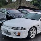
Ah ok the turbos looked standard when I had a look at the car. Didn’t look it was ever removed but very hard to tell. These are the best photos I have if it helps identify anything. I know it’s basically impossible to see anything 😅
-
 Its only a guess, but it likely doesn't have cams; probably a Z32 Air Flow Meter and slightly larger turbos. It was very common to chip and remap the standard ECU back in those days, but it means you won't be able to modify it further without replacing the ECU
 -
Amazing! Thanks for sending this through. Feel safer knowing a reputable shop worked on the car before I decide to purchase. Do you know much about how they would have tuned their cars through chips? From what I know, the car sounds like it has very small cams, the usual exhaust and air filter mods and a chip in the stock ecu. Motor sounds healthy and starts right up with no hiccups or smoke, compression is around 140-145 cold (wasn’t able to test this while it was warm)
-


Recommended Posts
Create an account or sign in to comment
You need to be a member in order to leave a comment
Create an account
Sign up for a new account in our community. It's easy!
Register a new accountSign in
Already have an account? Sign in here.
Sign In Now