

Announcements
-
Similar Content
-
-
Latest Posts
-

By joshuaho96 · Posted
Isn't there a fitting on the back of the balance tube? That's what the OEM boost gauge uses. -
 Getting a decent signal from all 6 throats is a challenge. I don't know for sure, but I suspect that the stock balance tube is not ideal for it. I have done it on an ALFA 4 cylinder (about 35 years ago, so don't ask for too many details). We drilled 4x holes in the manifold runners, put in some fittings and ran hoses to a decent sized (I think it was about 20mm diameter) pipe that ran the length of the inlet manifold. So, it was quite a decent volume. There is a "tuning" balance to be found between the volume of the common plenum on such a thing and the diameter of the pipes running from it to the runners. You need the volume to be large enough to damp out the sharp spikes in pressure signal you get as each runner gets sucked on by its cylinder, but not so large that it becomes too slow to respond to actual changes in MAP. And you need the hoses to be small enough to transmit the signal quickly, but not so small that they delay the signal. You might have to have more than one go at it, if there isn't any actual success based wisdom to be had here. Hopefully there is. Anyway, I would not do it on only a couple of cylinders. I would also not care about "permanently modifying a part". Just bloody drill holes and make stuff better. There is nothing sacred about any GTR unless it is a genuine museum piece that you shouldn't be modifying at all anyway.
 -

-
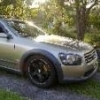
 The strange thing is this is a URAS front bumper (or clone of it). The bumper actually does not sit flush with the GTT hood - You need the addon to make the hood 'long' enough to reach the bumper. I have no idea why they didn't incorporate this piece into the bumper itself.. instead of sticking it to the hood instead.
 -
 Another thought on this OLD topic: When you paint your bonnet lip, leave a small unpainted back lip/line along the back of the lip, where it rests on the bumper. That way, the line in the back is much more prominent than the gaps in the front/under the lip - and it breaks the hood-to-bumper connection at the "correct" place, when comparing to a GTR. I'm gonna do this with mine this week, so stay tuned for pics!
-


Recommended Posts
Create an account or sign in to comment
You need to be a member in order to leave a comment
Create an account
Sign up for a new account in our community. It's easy!
Register a new accountSign in
Already have an account? Sign in here.
Sign In Now