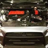
Knock sensor harness location/access?
Announcements
-
Similar Content
-
Latest Posts
-
Update: I got the magnet out. I bought 3 different flexible magnetic reach tools, but none of them worked. The magnet on the tip was all less than 2lbs of force, so i had to buy a special cylindrical magnet that had a pull force of 9lbs. The magnet finally came in the mail yesterday, so i got under the car to get to work. The super strong magnet isn't that long, so i only have about 1 finger pinch lengths to hold it. I was so scared when i was going in the hole, that the 9lb magnet would just fly away inside the oil pan never to be seen again, but i had my butt cheeks clenched and finger gripped on that thing so tight, i managed to get it to suck the other magnet out. It was a victory for me last night.
-
Yep, pretty much what you said is a good summary. The aftermarket thing just attached to the rim, then has two lines out to valve stems, one to inner wheel, one to outer wheel. Some of the systems even start to air up as you head towards highway speed. IE, you're in the logging tracks, then as speeds increase it knows you're on tarmac and airs up so the driver doesn't even have to remember. I bet the ones that need driver intervention to air up end up seeing a lot more tyre wear from "forest pressures" in use on the highway!
-
Yes, but you need to do these type certifications for tuning parts. That is the absurd part here. Meaning tuning parts are very costly (generally speaking) as well as the technical test documentation for say a turbo swap with more power. It just makes modifying everything crazy expensive and complicated. That bracket has been lost in translation many years ago I assume, it was not there.
-
Hahaha, yeah.... not what you'd call a tamper-proof design.... but yes, with the truck setup, the lines are always connected, but typically they sit just inside the plane of the rear metal mudguards, so if you clear the guards you clear the lines as well. Not rogue 4WD tracks with tree branches and bushes everywhere, ready to hook-up an air hose. You can do it externally like a mod, but dedicated setups air-pressurize the undriven hubs, and on driven axles you can do the same thing, or pressurize the axles (lots of designs out there for this idea)... https://www.trtaustralia.com.au/traction-air-cti-system/ for example.... ..the trouble I've got here... wrt the bimmer ad... is the last bit...they don't want to show it spinning, do they.... give all the illusion that things are moving...but no...and what the hell tyre profile is that?...25??? ...far kernel, rims would be dead inside 10klms on most roads around here.... 😃
-
By joshuaho96 · Posted
You're just describing how type certification works. Personally I would be shocked to discover that catalytic converter is not in the stock mounting position. Is there a bracket on the transfer case holding the catalytic converter and front pipe together? If so, it should be in stock position.
-


Recommended Posts
Create an account or sign in to comment
You need to be a member in order to leave a comment
Create an account
Sign up for a new account in our community. It's easy!
Register a new accountSign in
Already have an account? Sign in here.
Sign In Now