

Announcements
-
Similar Content
-
-
Latest Posts
-
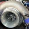 I can see between the water jacket and cyl 3 there wasn't a hard line of combustion gas. It certainly appears that the issue is coming from there. Yes, checked the tension. All at 100ft lbs where I set them 5 years ago. These blocks can crack but generally when they have been over bored. Mine is only 0.5mm oversize at 89.5mm. They break between cylinders around the 91mm mark. No sign of that with mine. My gut feeling is the head gasket lifted a while back when the studs stretched and i bandaided it by retorquing the studs. It's finally let go.
 -

By TurboTapin · Posted
My Nismo 1.5 churps a bit on reverse turns when cold, but besides that feels like a stock diff. -

-

-
So, version 4 intake is on its way I was looking at these a while ago but at around $200 or more it was a little pricey for something that might not work, but, I had it in my watch list, but, I got a message saying it was on special, and I had a code thingie to use, it eventually came in at $120 delivered, so BAM, BUY NOW.....LOL I'll need to have a look when it arrives but I feel it will "look" better than what I currently have, as it comes with a PCV fitting, so I will be able to get rid of the alloy pipe that goes to the throttle body with the PCV fitting Well, that's what the voices in my head are telling me Oh, and this happened today Yeap, it was a Trojan, and it was cheap, so I headed back to the hardware store and actually spent a little bit more on a heavy duty, one that was actually recommended by a plumber mate, a Cyclone one with a fibreglass handle that is actually rated for clay The broken shovel will eventually be "modified" into a short handle shovel
-


Recommended Posts
Create an account or sign in to comment
You need to be a member in order to leave a comment
Create an account
Sign up for a new account in our community. It's easy!
Register a new accountSign in
Already have an account? Sign in here.
Sign In Now