Jump to content
SAU Community

Recommended Posts

ok heres a couple of pics of my best lead so far in finding a good solution for how to do the pcb and box. it would be a double serial adaptor box, which one side plugs into ur serial port on laptop, and the other side plugs into a cable from the consult port.

this has the added advantage of being that u can keep the consult plug connected 24/7, and just disconnect the adaptor box from the cable whenever u arent using it. ive been meaning to try figure out whether we have a switch or something to turn it off, but this seems to be a much more elegant solution.

the box would have female connector on laptop end (as laptop serial port is male) and a male on the consult cable end.

post-4553-1125912415.gif

post-4553-1125912460.jpg

  • Replies 102
  • Created
  • Last Reply

Top Posters In This Topic

ive uploaded a quick list of parts and likely costs, this should hopefully represent the maximum cost it could be, but most likely will be able to bring them down a bit by buying in bulk or from somewhere else (i think i know someone who might be able to get me stuff a bit cheaper). the max232 chip especially should only be about half the cost jaycar sell it for if i get it elsewhere

http://users.bigpond.net.au/newkleer/diyco.../components.xls

as you can see at this point the total is > $60, but id hope the final one would be down around the $50 mark including postage (if i buy stuff in bulk)

ive got some of those adaptors in the above pic, and if theres no problems fitting pcb with components in it, then ill go ahead with finalising the pcb. im aiming for the first run of components to be about 25, can always sell on other forums if theres left overs, so not too worried about minimum numbers or anything

ill probably make a new thread in group buys or something after pcb is made and ive built one and do a writeup/instructions of it. im not quite sure yet though if it would be better to only sell kit to a few and make sure they dont have any problems building it that i hadnt thought of (or missing components or whatever)

Edited by NewKleer

recieved 25 of the adaptor boxes (black) this week (ended up costing a bit more than a thought as i forgot to factor in exchange rate and shipping). at this point im estimating around 45$ for final thing, ill probably aim to make it an even $50 including postage (which i can buy in lots of 10 or something)

external dimensions are roughly 70x42x20 (maybe 80 long when u factor in serial connectors on the ends), so roughly same as previous one but slimmer. hopefully this weekend i can have a shot at a final pcb layout for it

heres some more pics. this is the final draft. board fits into box with connectors on end like in pic i posted above.

also managed to to fit a power led on board, with a 3mm led and with a bit of bending (i imagine), it should be able to poke thru the little screw hole in serial connector, so that u can see the power is on before u connect the adaptor to the serial port of ur laptop, thus no drilling required

close to definite that cost will be $50 + postage for final kit if all goes well

post-4553-1126973902.jpg

post-4553-1126973914.jpg

post-4553-1126973930.jpg

Hi,

Wow this look awesome. I dont know alot about electronics, but i can solder (managed to build a couple of digital tachos previously). Definatley put me down for a kit in the next available run!!! :P;):P

decided to rearrange it a bit and add in the send/receive leds out the other end of the connector. pics are a bit bigger this time. also put a lot more info on the pcb itself so it alone would be enough (if readable :() to put together

as far as im concerned this will be final layout, excepting mistakes (and a check to make sure components will fit ok). sending this off to get checked by pcb manufacture place, id estimate a few weeks and itll be ready (if no mistakes or any problems arise)

post-4553-1127020800.jpg

theres enough software out at the moment which means making any more isnt really worth the effort. for free software, calumsult and scantech nissan are a pretty good combo, add datascan if you dont mind paying for it

at the start of this year i had a go at making a combined comms/consult access (for both pocketpc and desktop), and got ecu serial number, and reading sensors out of the way, but didnt have enough time to do the rom reading. main problem however is pocketpc graphical stuff is pretty limited and i had problems with it

ill be looking to continue with that perhaps after this semester of uni, or i might have a go at an lcd display, havent worked out which yet. the lcd display would be more promising as it would be more of a permanent thing, whereas laptop software isnt something u use permanently, so its usefulness is limited aside from specific information gathering/diagnosis.

my thesis is coming up at uni next year, so i was looking into possibilities to do something with consult for that. dont want to get too far ahead now, for the time being i want to get this kit happening before anything else

Edited by NewKleer

pcb's are in process of being manufactured, and ive ordered nearly all needed parts

attached is a rough placement of components on a pcb, will closely resemble how the arrangement will be on final one (most are half a position off in x and/or y, but pretty close)

post-4553-1127454697.jpg

Edited by NewKleer
  • 3 weeks later...

i should have all parts and pcb's sometime this week!

edit: they came today! unfortunately wont have much time over next few days, but before end of week hope to make one and test it and see it all works well, but so far so good

edit2: they mixed up the serial connectors so need to wait for proper ones to come

post-4553-1128925880.jpg

post-4553-1128991119.jpg

Edited by NewKleer

heres my construction guide minus any photos. if anyone wants to have a read of it and let me know if, assuming they were making the board (and have the diagram pic as above - note "hood" on pic = C9 capacitor) whether they cant understand anything or would need some parts better written.

i made one last night as a test (pic2 above), havent had time to actually try it yet though. missing two resistors near the leds on the right, but apart from that its finished

construction.txt

hey can i get these already made? id be real interested in getn one ready to go if i have the neccesary cables. not real confident in making one of these you see....

i put one together the other night. found out that in my last minute rush to add the yellow led to the pcb when designing it, that i got it to hook up to ground instead of power (but being my first shot at custom pcb, surprised i didnt make any other mistakes). theres a workaround to fix this (cut a track and then solder two pins together with a bit of wire), but in my opinion its probably not important enough to worry about this LED - more important are the power one and the send from ecu (to pc) led.

either way ill include needed parts and update the guide to explain how to fix this if for some reason yellow led is important. apart from that, im quite pleased about how its progressed so far. ill contact people individually about those who will be the guinea cops, but at a minimum ill need them to read the construction guide in advance and let me know if they think its clear enough to work off and so on.

last thing im worried about is the voltage regulator and transistor being quite a tricky soldering job - the distance between the legs is quite small and would be easy to solder two legs together, so not sure what i can do to help with that. i spose if ur not confident in getting that done properly, i could probably solder them to the boards before sending off (just makes it hard to solder the shorter components though, ie they fall out of the holes easier if they arent flat against whatever youre soldering on).

will be busy until next week so i dont imagine doing anything till then (and missing parts wont be here till around then), but ill contact those who've expressed interested about whether they want to be one of the first few to give it a shot and give me some feedback on construction

at this stage i wont be looking to make pre-made ones (whole point of this was cause i didnt have time to make them all myself), but there may be others out there down the track that might put them together for a fee

Edited by NewKleer

few more pics now i worked out how to focus the camera better!

edit: added two more pics, of final board + cable. couple resistors missing from the board near led's, but apart from that its complete

post-4553-1129287413.jpg

post-4553-1129287465.jpg

post-4553-1129287829.jpg

post-4553-1129287993.jpg

post-4553-1129288424.jpg

post-4553-1129432656.jpg

post-4553-1129432683.jpg

Edited by NewKleer

Create an account or sign in to comment

You need to be a member in order to leave a comment

Create an account

Sign up for a new account in our community. It's easy!

Register a new account

Sign in

Already have an account? Sign in here.

Sign In Now


  • Similar Content

  • Latest Posts

    • I'm seeing torque specs all over the place for the OUTER tie rod, but none for the INNER tie rod, where it connects to the steering rack. Even in videos, people are just tightening em up as much as they can with a wrench and that's it. Anything tightened down without torque makes me nervous. Anyone know what the spec is for it?
    • Hope you had a great time here in our tiny country.   The JDM scene we have here is quite small, it's mostly BMW, Volkswagen with burble tunes haha. But the few JDM cars we do have in the scene are pretty nice. Some of my friends drive cool s14's too. Both built engines, red one makes abt 500, blue one abt 400 i think?
    • Ye good idea , would have never thought of something like that. Might aswell do it to every pulley and the balancer while I’m there 
    • Use an LS1 or similar, via kit like Frenchy's. But.... It's probably not the alternator. It sounds like belt squeal, which would be because the pulleys are glazed. Rub every groove on the pulleys with 120 grit paper. Report back. Oh, and new belts afterwards too. The old new ones will be shitted up already.
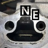
    • Hello all I have 2 r34 sedans , one turbo one na, only recently aquired the na 34.  Man what is with these things.... My turbo 34 started sounding like a super charger, it was screaming at anything above 4000rpm , I took the alternator apart and replaced the front bearing which is the only one I think you can access and it did not fix the issue so presumably the bearing in the rear of the alternator is gone. ( diagnosed it was the alternator by taking off the aux belts one by one to figure out which pulley or bearing it was )  My friend gave me one he had lying around, Installed it , it did not squeal for maybe 500kms and now its started to squeal again briefly on startup  Recently got an na r34 and I replaced the timing belt, water pump + all the auxillirary belts. Runs amazing but it suddenly developed the same squeaking problem but significantly worse, Ive had my neighbour come down screaming at me because it was waking her up everytime I moved the car. It takes a good 2 minutes before it quietens down.  Im yet to diagnose where its coming from but im fairly sure its coming from the alternator aswell. My question isnt about how to fix it but rather where can you get a new alternator for an rb25 neo??? Ive searched everywhere but I havent been able to find a direct fit oem type replacement thats not genuine. All the automotive stores sell an oex one - BXA035 - which I picked up for cheap through a friend with staff discount , got it home only to find the connector is completelty different.... As far as im aware bxa035 is for rb20/30's and after a bit of figuring out the bxa035 has an ev14 type connector, which is tiny compared to the rb25 connector. I actually had an ev14 connector lying around which I was considering just replacing the bigger plug with to get the alternator working but the bxa035 is rated for 70amp vs the rb25 alternators are 90amp ( or so ive been told ? ) That paired along with the fact im about to install an amp + sub in the back and I have the stock sized small battery Im not sure itll do the job unless anyone has another opinion?  I know and have seen all the websites selling the ls1 alternator conversion kit but I am not going down that route, nor do I have the money to. Hopefully I can figure out how to get 2 brand new alternators for both cars. I would buy second hand which there seems to be many of but considering how common this seems to be im sure If I installed a second hand one it would start squealing in no time  Or even better if anyone knows how to fix the issue directly with the alternator itself... Any input appreciated Thank you     Link for bxa035 connector picture
×
×
  • Create New...